|
3 December 2017
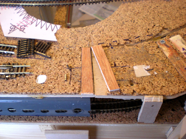
Some time was spent on getting the platforms at
Evercreech Junction just right. After a couple of false starts I
finally produced this version in balsa wood (easy to shape) toped
with a layer of cereal box card (easy to shape after the balsa has
been shaped, and easy to paint and stain. The ramps, though, needed
to be propped up with more card, like this:
Then the platforms were painted lightly in several coats and three
different greys until I found a shade I was almost happy with.
Elsewhere, more scenery formers were added between the colliery and
the main line out of Evercreech.
Then one of the curved storage lines in the colliery area was taken
up and relaid as a straight line. Having found a good modeller's
article on the colliery I now have a much better idea of how this
area should look.
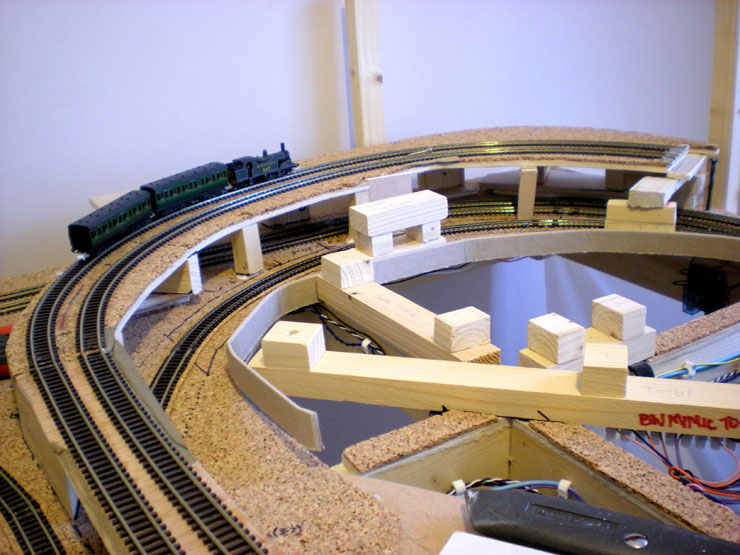
Here's an overview of the entire Evercreech Junction (EJ) area at
the front of the layout, with painted platforms in place faced in
brick and stone paper, and both water columns in place (although the
farther one would soon be taken up temporarily (aka accidentally
knocked out of its housing).
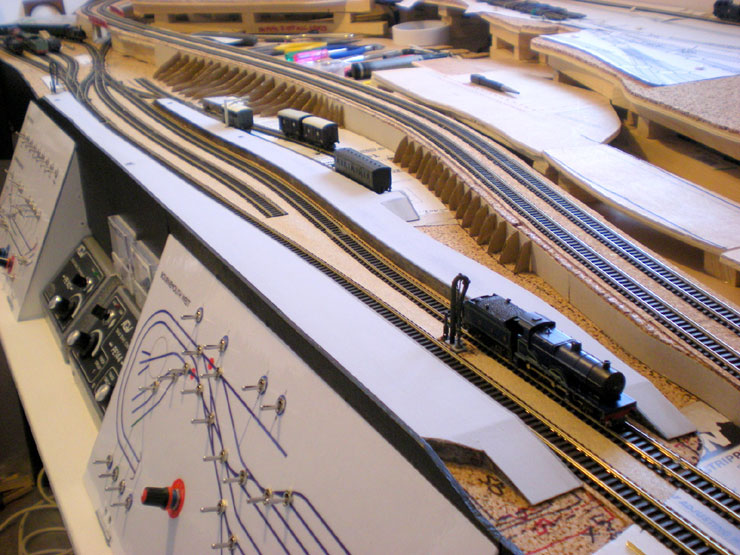
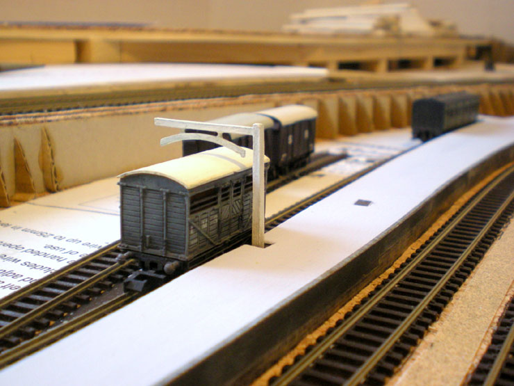
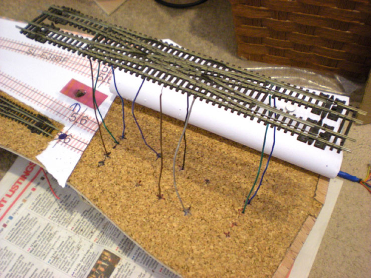
The loading gauge for EJ Goods has been permanently fixed in place.
Underneath, some more of the route setting relays have been put in
place.
Needless to say, I didn't wire these in. They're an unexplained
mystery to me!
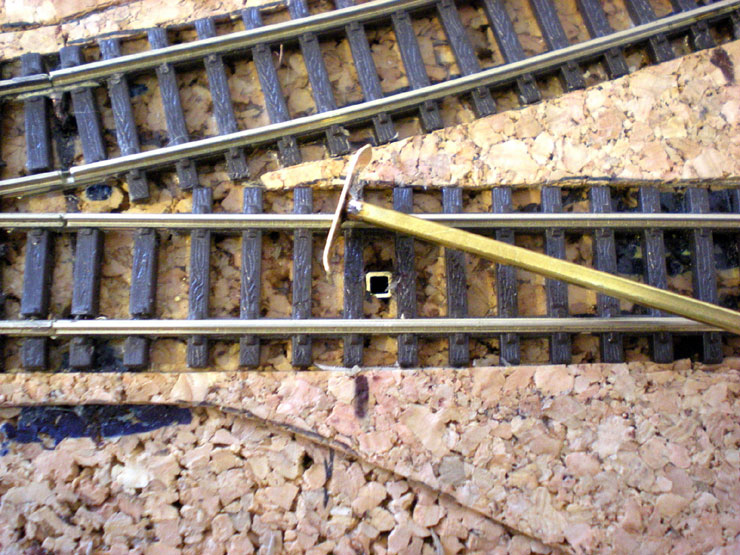
Here are the beginnings of an experiment to produce an uncoupling
ramp. The brass square rod which fits inside another rod was easy
enough, as was soldering the brass ramp to the top of the thinner
rod. The servo underneath the board which operates it will take much
longer.
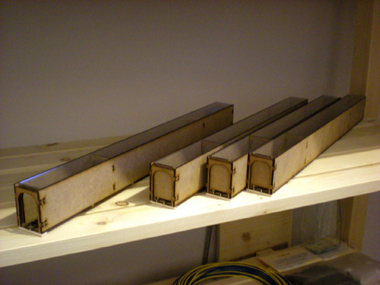
Much easier to complete were three more of the kit-built rolling
stock cartridges which will sit under the fiddle yard.
At EJ station I decided to add a bit of a raised roadway at the back
so that it comes up to meet the back of the stationmaster's house.
Visible at the bottom of the photo is a white metal post for the
level crossing, but more of that another time.
And now for a bit of major work on the incline.
The top section from the bridge up to the joint with the MPD board
has never worked properly. I decided it was time to rip up the
entire thing and start again. But first I needed to store some
rolling stock prior to removing the fiddle yard. That meant a few
extra storage trays, and at last I have enough stock of the same
type in one tray to be able to label a few of them.

With the stock removed, I was able to remove the controller section
from the front of the layout, and then detach the fiddle yard and
heave that out into the spare bedroom (it's really a two man job, so
heaving it out solo requires a bit of effort). Then the layout could
be wheeled forwards so that I could get around the back (after
refitting the controller section so that I could send test trains up
the incline).
Here's the old incline, with the very bad track connections at the
bottom and the Grand Canyon jump across to the MPD board at the top.
I've already started removing support blocks and thinning them by at
least half of their original width to maximise the amount of track
underneath that can be reached.
The old board joint at the top of the incline was on a curve in the
track - never ideal - and it caused some stock to derail. Now I cut
a chunk out of the MPD board to attach to the incline and change the
place at which the two met.
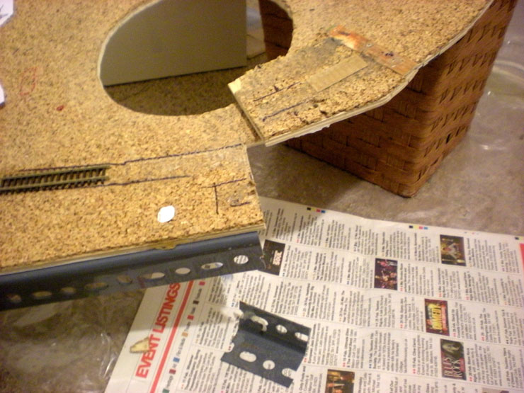
The MPD board off-cut was clued and screwed to the incline and an
extra support put in place underneath. That also meant sawing off
part of the metal support bracket under the MPD board.
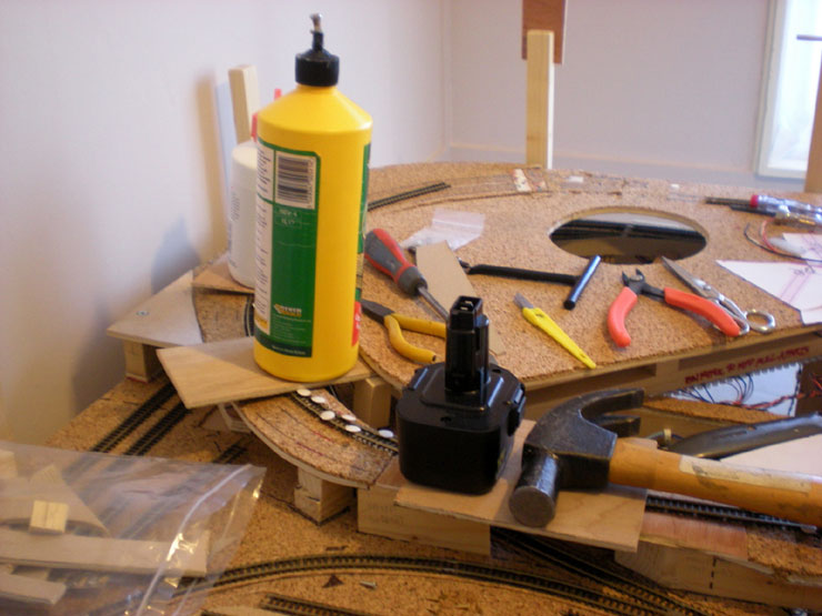
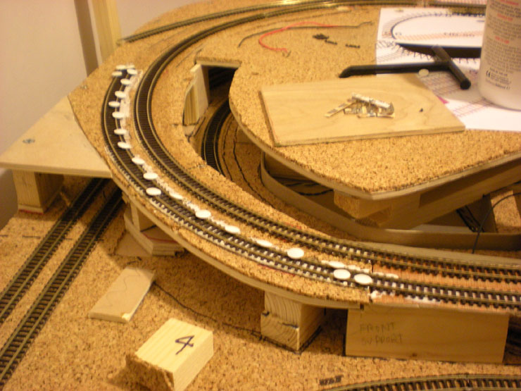
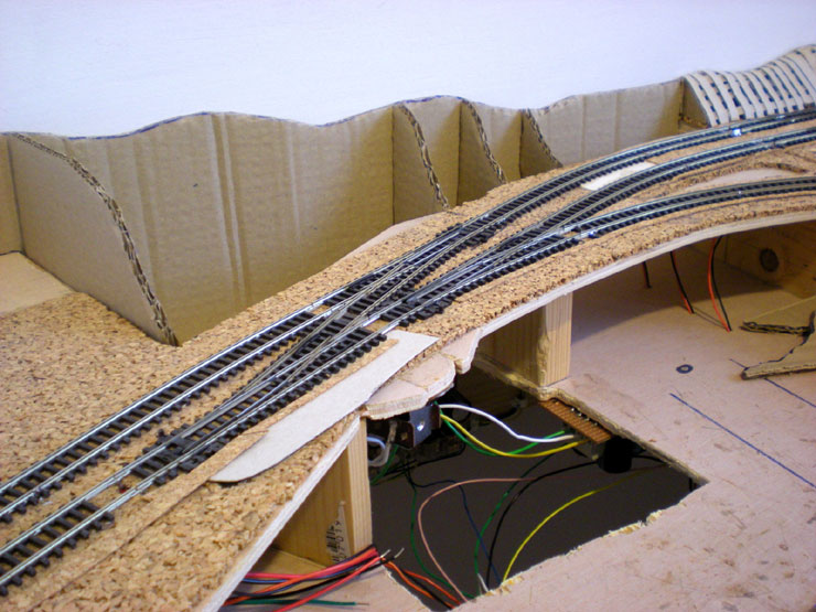
With the board joint now in place and level across the very much
smaller gap, I could concentrate on laying the inside track (which
would have the tighter radius). Constant testing produced a curve
which was free of any wheel lock-up, and placing the track joint
beyond the right-hand side of the bridge (under the hammer handle in
this photo) meant no awkward rail joiners just where the curve
tightens up.
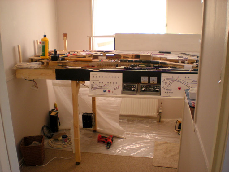
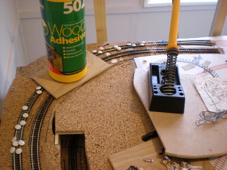
While we're waiting for the glue to dry, here's a shot of the main
baseboard, pulled out into the middle of the room and with the
controller section loosely reattached.
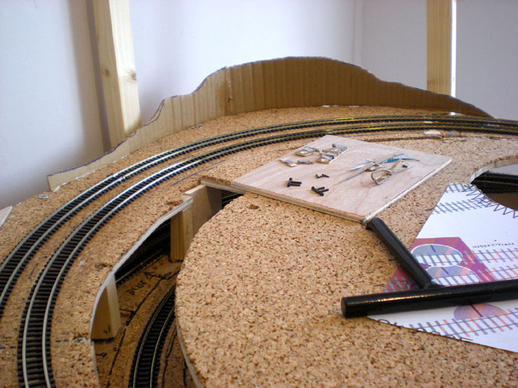
At the top of the incline I took out the cork and replaced it with
hardboard of the same thickness. This is where the board joint will
go.
Extra droppers were soldered under the track so that both ends of
the incline have a power feed, and rail joiners on a tight curve
aren't the only way of ensuring that power reaches the top of the
incline. The track would also be soldered to the blocks which were
salvaged from the old incline top (I had to - it's all I have of the
stuff).
After much track bending and testing with powered locos, I had a
top-most part of the inner track that I was happy with, so this
could be glued in place. It would have been next to impossible to
take it up and use Copydex and still keep the perfect positioning,
so I left it pinned in place and dripped in wood glue mixed with
water.
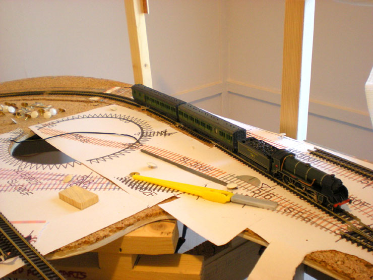
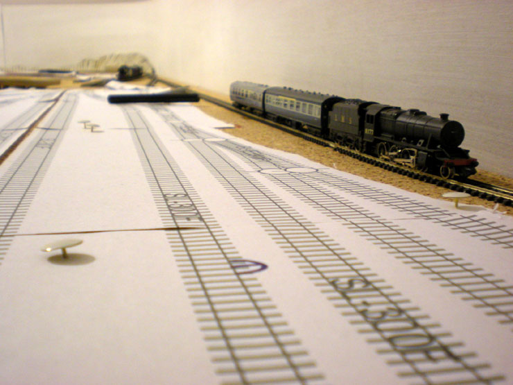
Twenty-four hours later I had an inner track incline that even a
King Arthur could negotiate with ease. This test train also managed
to achieve a new record for the furthest a powered train has managed
to get on the upper level.
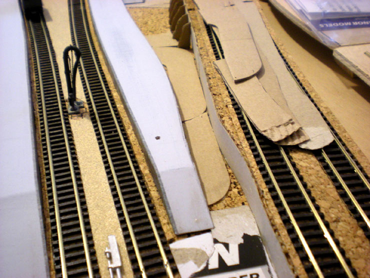
Next it was time for the outer track to be tested and laid. This one
was a little easier (not necessarily saying much!) as the curve was
a little more generous. There's also a little banking going in under
the track with the light grey card to offset the slight outwards
tilt of the track without it.
The next day the top section of track was laid (more testing, more
track bending, more success). I did all the soldering across the
board joint at the same time, much more neatly and unobtrusively
this time than I did before.
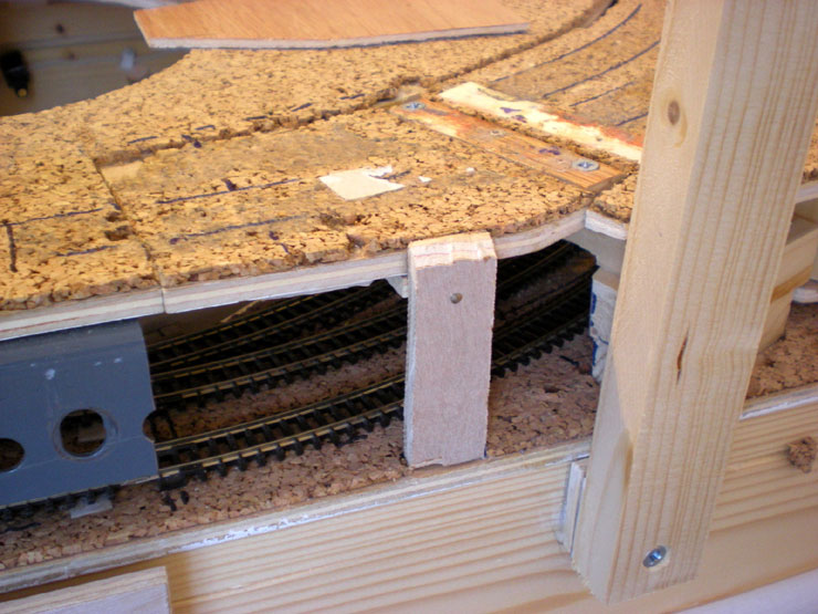
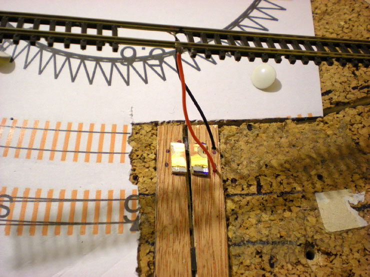
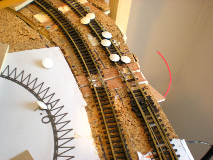
Here's a close-up of the board joint while the glue was still
drying. The red wire is another extra feed wire which would be
connected to the main circuit once the layout was back in position.
The next job will be to saw across the tracks in the middle of the
board joint to separate them. I've already done the inner one here
and it's still pretty perfect.
Cuts done, the track still lines up perfectly and smooth running has
been achieved along the entire upper section of the incline. That
lot took a week and-a-half of various sessions to complete. I also
started adding some scenery formers in celebration.
1 April 2018
Nothing new has happened with the layout this year,
but that doesn't mean I can't catch up with the last of 2017's
progress.
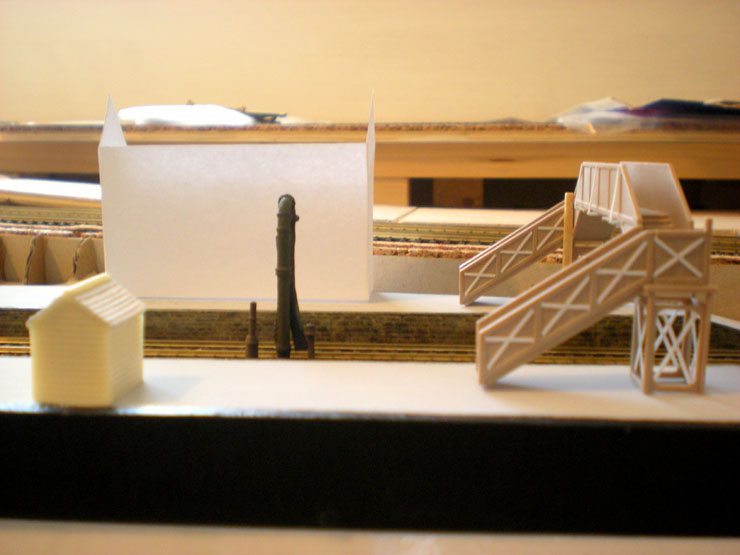
After finishing off the incline rebuilding work
(see above), I managed to produce a test print of the
stationmaster's house for Evercreech Junction (EJ). There are no
details on it at this stage. It's just a shell so that I can gauge
the size. The footbridge is accurate so I can gauge it against
that... and the building is a little too tall. Back to the design to
trim off a couple of millimetres and also to reshape the rear of the
building.
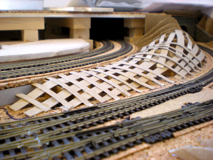
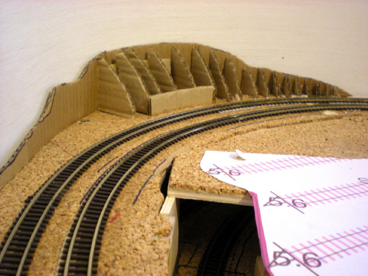
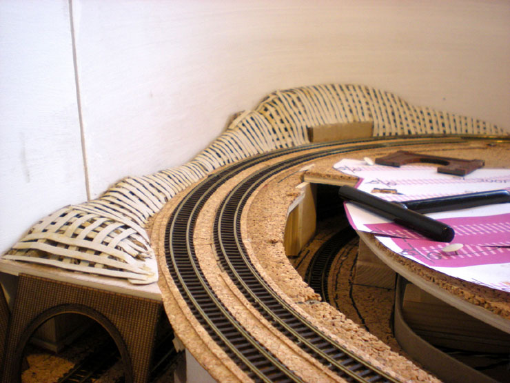
On the scenery side of things, some progress was made with two
layers of card strips across the vertical formers. This hill would
be ready for some landscaping work to go over the top if I only knew
how the hill was supposed to meet the upper level. I can't do that
until the track is laid up there and I know where the station
buildings are going to go.
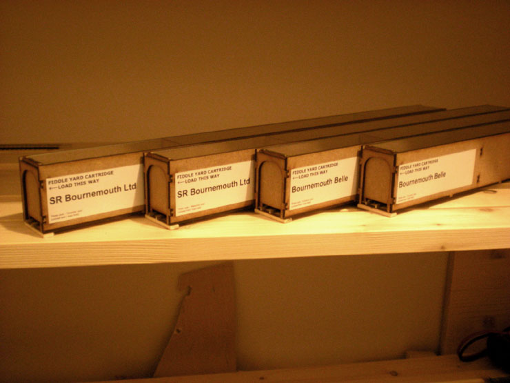
To add to the initial test run at building a rolling stock
cartridge, I've added three more of them, all MDF kits from Mill
Lane Sidings. You can see that they're labelled up now, two for the
Southern Railway's 'Bournemouth Ltd' service using Maunsell coaches,
and two for the Bournemouth Belle, using Pullmans. They make it much
easier to roll-on/roll-off stock onto the fiddle yard - essential
when the layout actually becomes operational... one day.
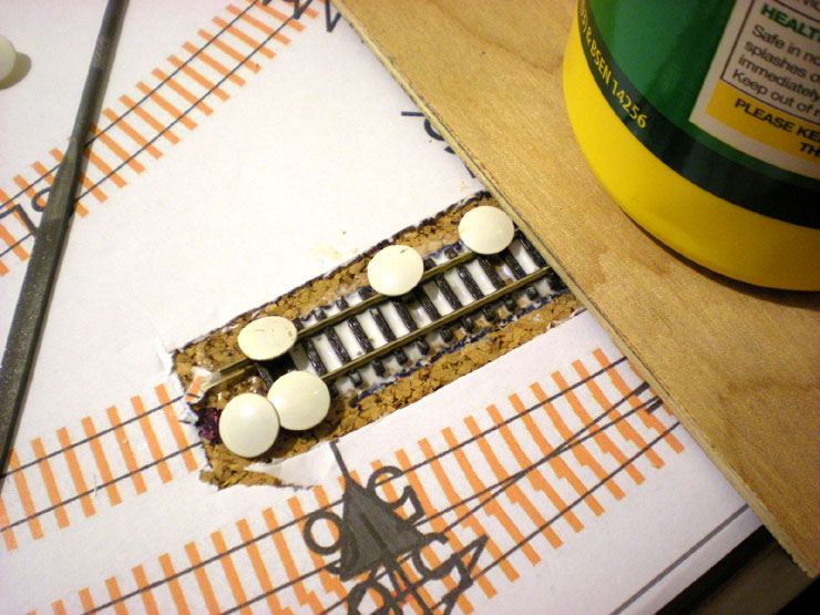
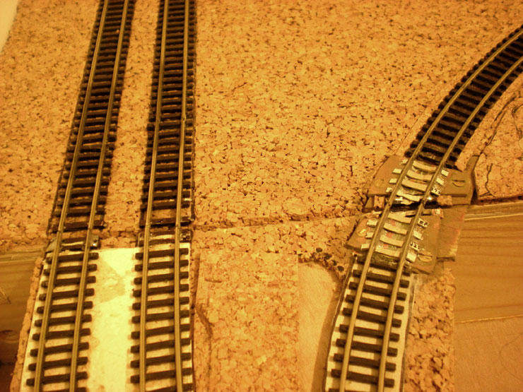
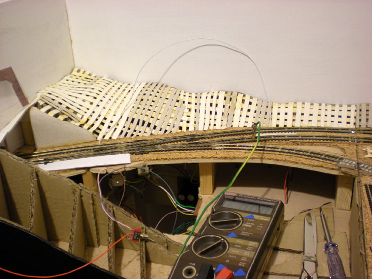
When the top of the incline was fixed up, I laid down card sleeper
'tops' across the track over the board joint. Now I've done the same
on the Highbridge loop at the front of the layout. It looks a
little rough at this stage but I'm hoping that when a thin layer of
ballast goes down in between the sleepers, it'll look much better.
More scenic work could take place elsewhere, this time on the
rebuilt incline. The back 'corner' - actually a curve on the outside
of the rail curve - got some of its card formers and the backing for
a sleeper-built retaining wall. This corner will be filled with
pine trees and purple heather, both well known for living in the
Bournemouth area.
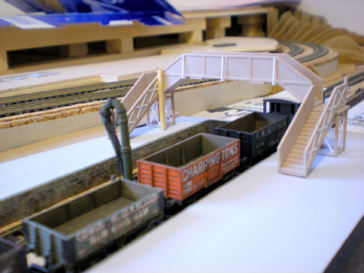
I don't think I've included a proper shot of the EJ footbridge yet.
So here it is. The single matchstick glued into the corner was
actually part of the real bridge (a wooden beam, not a matchstick).
In fact there was one at each corner, added by the Southern Railway
to secure the steps to the replacement overhead section when that
replaced the
original wooden version in the
1920s. The one matchstick here will be the same colour as the
footbridge when it's painted, but the other three will be bare wood, so I can't add them until painting is complete.
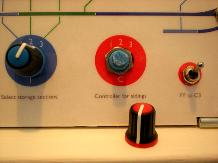
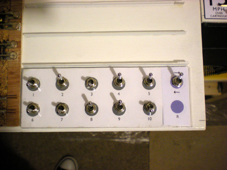
Another job done was to add an extra stop to the 'Controller for
sidings' switch. Settings 1, 2, and 3 are to determine which
controller supplies power to the sidings in two locations on the
lower level, but it's a good idea to add a neutral setting too just
in case no power at all is required. In effect, the neutral setting
acts as an extra isolator switch.
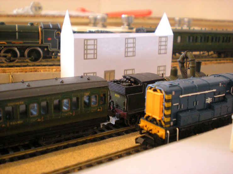
It's time to test version two of the stationmaster's house, this
time with sample windows and doors. It's a little shorter, but I
need to do a little more work on the rear so that it sits properly on the
pathway behind the platform.
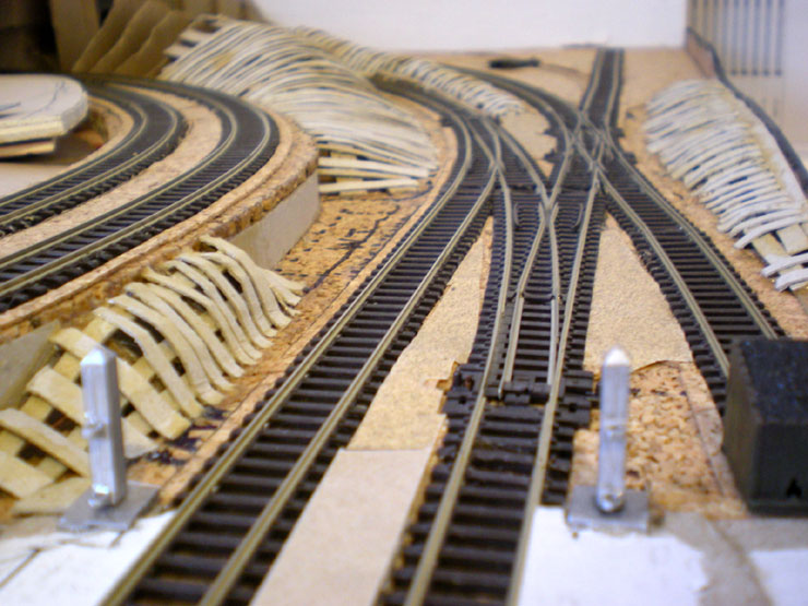
Final job of the year, to drill all the wiring holes for the
scissors crossover on the upper level. I'd love to get the upper
level working without having to worry about any wiring for something
as complicated as this thing, but nothing's going to get through
this without relays and points motors being installed. Maybe next
year...
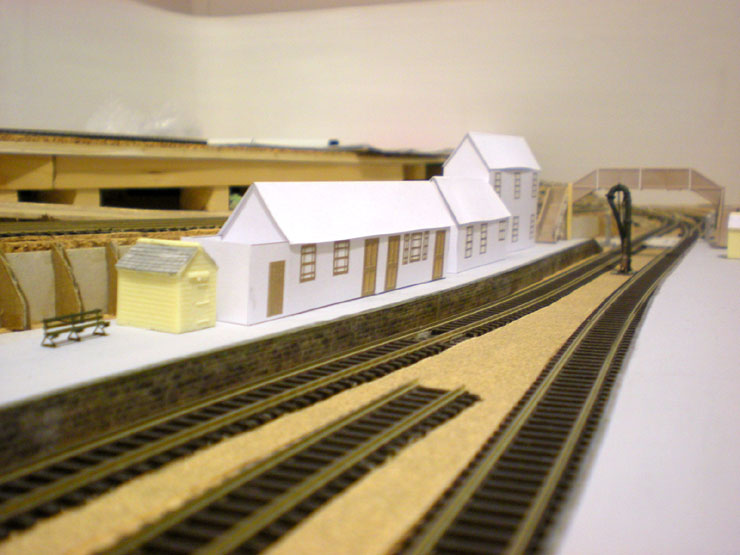
24 December 2018
There has been quite a bit of work taking place on the layout
recently. Mostly it's been scenic-related but there has been some
track laying too. And even some wiring (shock, horror). A fresh set
of Evercreech Junction (EJ) station buildings was printed off and
assembled to check heights and widths against the pretty narrow
platform. The waiting room nearest the camera still needs to be
shortened so I may have to remove a window.
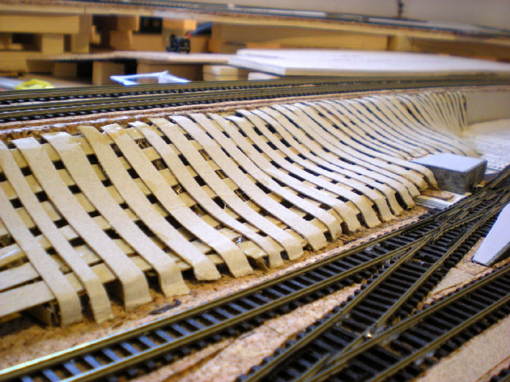
A lot of scenicing has taken place, usually at the rate of half an
hour or so at the end of the day. The gently sloping hill down to
EJ's goods sidings has been set up with card strips, blending in
around the cattle dock, just like the real thing.
The slope down from the incline where it sits behind the (eventual)
site of the goods shed is a lot less gentle, thanks to the fact that
there's not really that much space there.
Further down the line, much of the landscaping framework has also
been set up. The only bits I can't finish are the ends where they
will mask the upper level joints. The upper level's track and
platforms will have to be set up before I know what needs to be
hidden.
Also complete is the outer side of the upper incline. There will be
vertical sleepers in place in front of the flat piece of card
(extremely tall ones, by N gauge standards!). This is where the pine
trees will be placed that always heralded the arrival of S&D
services to the Bournemouth area.
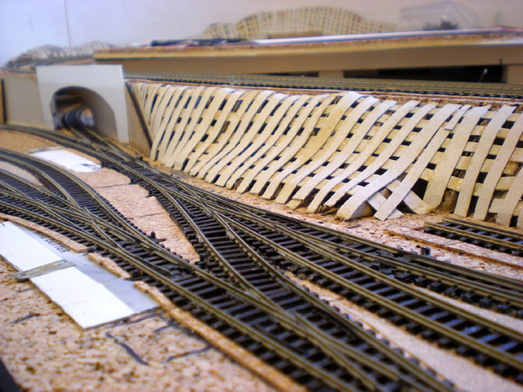
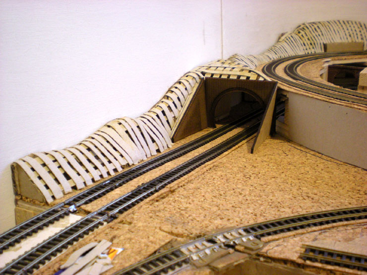
I gave up trying to find a proprietary tunnel mouth for the exit of
EJ under the incline. Instead I cut out a piece of plasticard to do
the job. In time it'll be covered in stone paper.
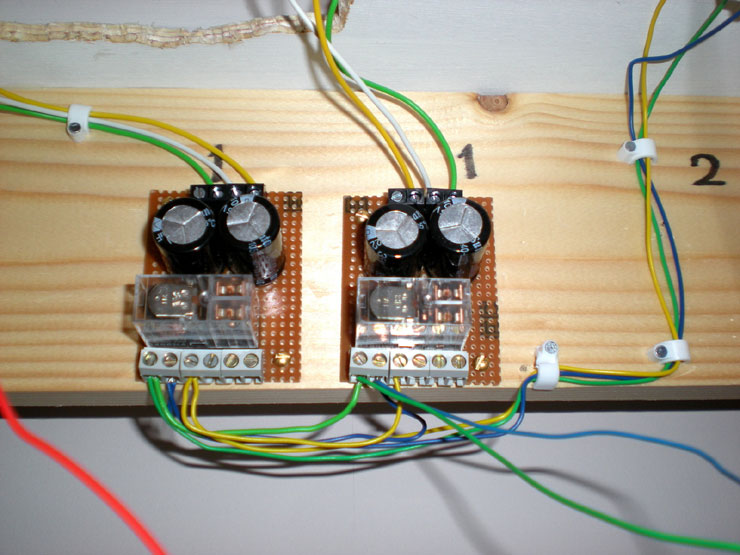
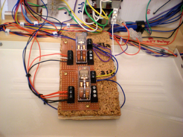
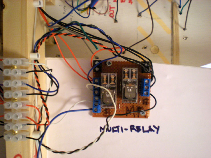
Underneath the layout some more tidying-up was done on the new
wiring, with this shot showing the double relays for the EJ goods
siding area.
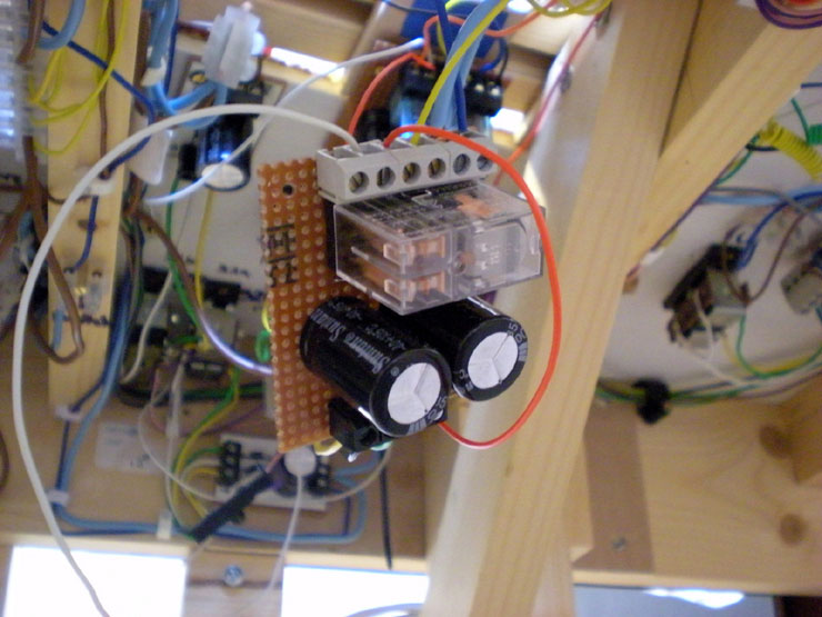
Something which took many visits to fully set up by my semi-tame
electrical genius was the multi-relay which controls much of the
route-setting work.
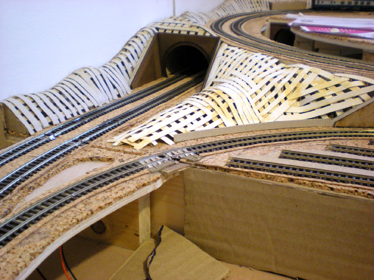
Back to the scenicing, the outer side of the main line between
tunnel and fiddle yard was given its slopes.
Then came a more complicated hillside build - the triangle between
main line, incline, and Highbridge loop (lower right).
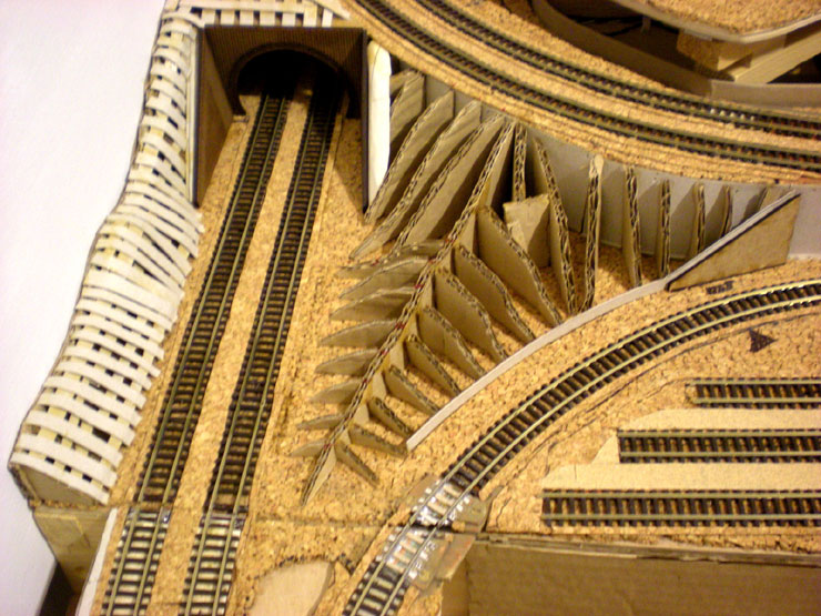
All the card strips were added onto the basic structure to give you
a good idea of what it'll look like when it's finished. The thin
strip of brown card will be a retaining wall.
Then I turned my attention to the small section of track between the
fiddle yard itself and the join with the main baseboard. The scenery
here not only has to disguise the raised track (or lowered
baseboard, if you prefer) but also the large and awkward hole. The
backing panel has already gone in and the first of the formers have
been added.
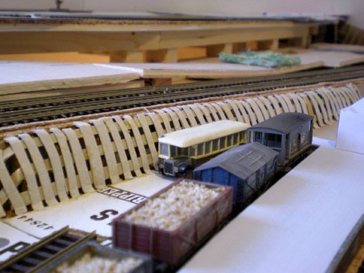
In the meantime, the first permanent track had been laid across from
the MPD upper level board to the Bournemouth West station board. The
very first self-propelled service to make the jump across boards was
hauled by the Stanier 8F. If that can make its way along a piece of
track with that long wheelbase then just about anything can.
Back to the fiddle yard board, and the hillside-building at the back
has been completed. The basic structure at the front has also been
started - possibly one of the most complex areas on the whole
layout.
The stray wires and SPDT switch are something else. The fiddle yard
itself had a bit of an electrical polarity problem because I'd
hard-wired permanent power for the outer track so that I only
depended upon the inner tracks to provide power across the
cartridges. This was fine when running a train in one direction
(into the fiddle yard) but caused a short-circuit when running a
train out on the other controller.
Paul came up with the suggestion of adding contacts under the
cartridges - a very sound technical solution, but one which would
have meant a fair bit of rebuilding work to all of those cartridges
that I'd already built. Instead I went very simple (which is just
about my level when it comes to electrickery). The new switch on the
fiddle yard panel (top right) with the direction arrows is my
contribution to the problem.
For incoming trains you flick the switch down, for the arrow
pointing left. For outgoing trains you flick the switch up. The
permanent power to the fiddle yard rails is switched to match the
controller being used and there are no more short-circuit
problems... I know. It actually worked!
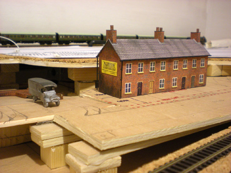
Back to the scenery - something that I haven't got around to
detailing yet in the
Infrastructure
thread yet is the building of this terrace of railwayman's cottages.
It's turned out pretty well for my very first card building in
almost four decades. I needed to get it finished so that I could cut
out a permanent base for it and then start securing the rest of the
road around this area. Here it is in place.
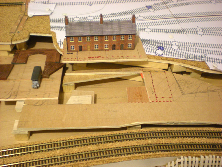
And here it is still in place on its removable base (which I can
take downstairs for some more comfortable modelling work on the back
gardens and front path). It slots quite easily into its 'hole',
while the rest of the wood around the site has been permanently
glued down. The next thing to happen along here will be the addition
of card formers for more hills. They will mask the joins between
baseboard and removable upper levels.
That's all still to come though. For now I'd like to wish you all a
very Merry Christmas!
|