|
1 September 2014
And so it begins...
This thread continues from the Layout Planning
section which can be accessed via the 'Layout Work' link at the top
of the page.
After a year and-a-half of plotting, planning, and
fine-tuning, construction work on the layout finally began a couple
of Saturdays ago. It took this long to get the main baseboard up
(literally) and running (on wheels, no less), with pesky work
getting in the way, but this is what I have so far.
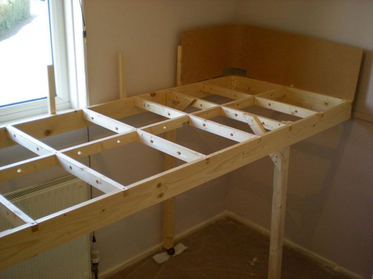
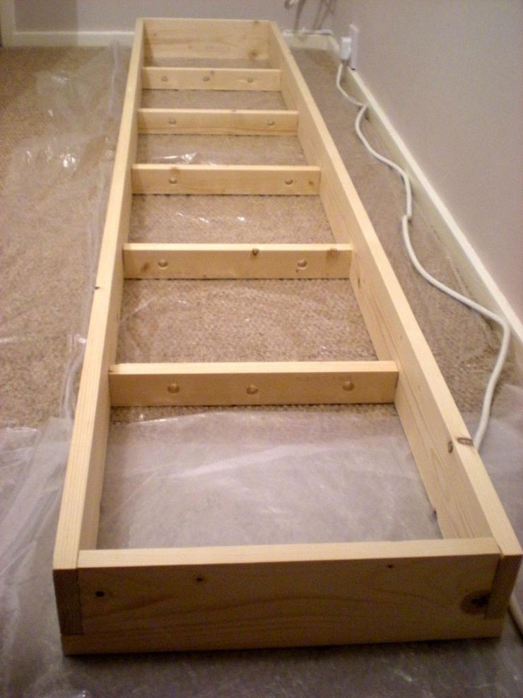
The first photo shows the main board, which is
2540mm x 800mm (that's around 8ft 4" x 2ft 7" for you
old blokes who can't cope with the modern world!). The framing
is solid enough to ensure no warping, hopefully, and the removable
backscene boards are propped in place by the vertical posts.
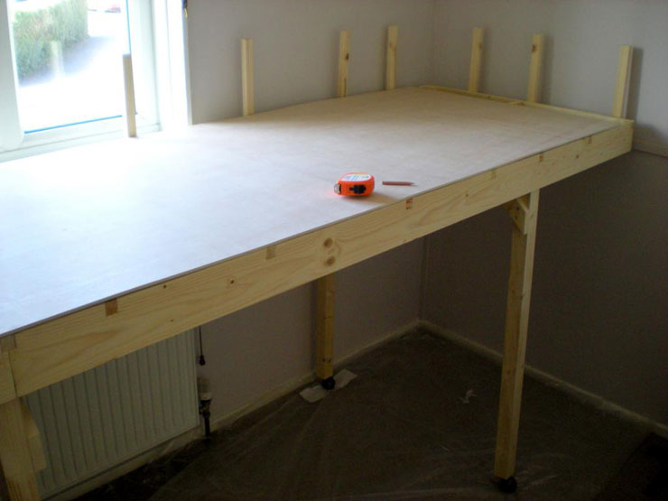
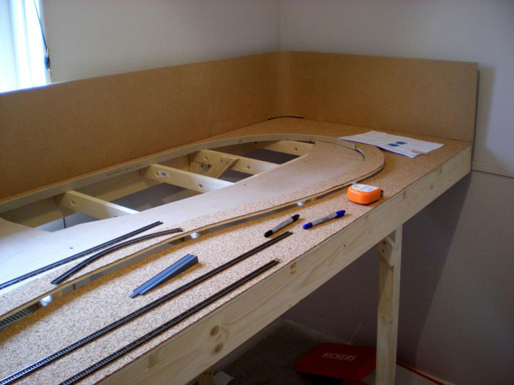
The second photo shows the layout with the main
board in place.
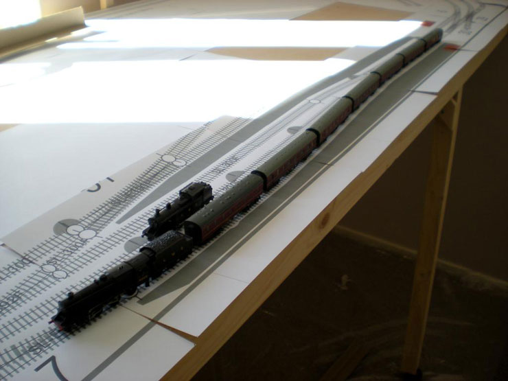
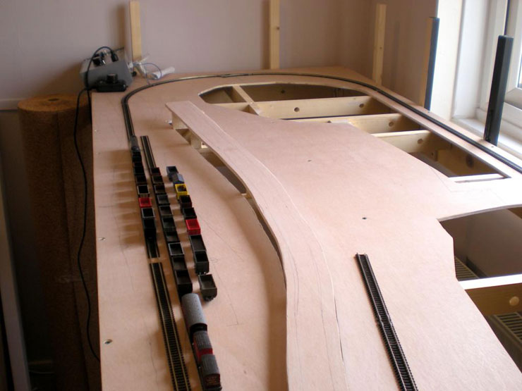
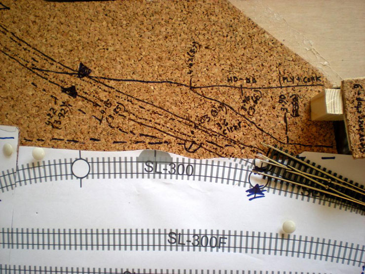
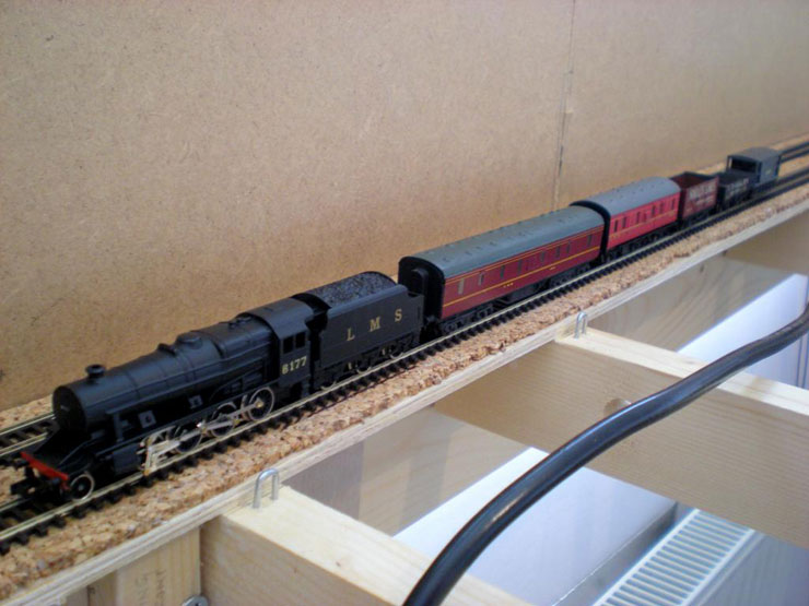
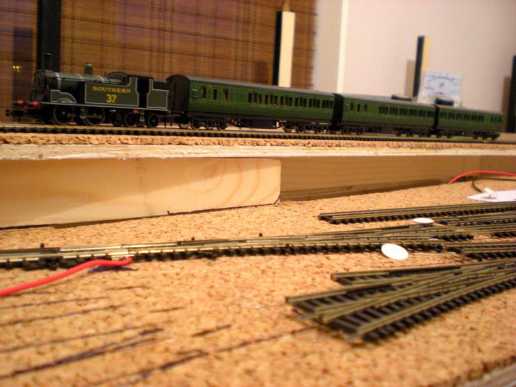
I also managed to translate the track plan from
paper onto the baseboard, and couldn't help playing trains with a
display shot of a full length 'Pines Express' at Evercreech (albeit
in late 1930s mode). That's in the third photo.
The next step is to mark the cut-outs for the
incline and the access points towards the back of the baseboard,
where the upper level will be sited. A quiet afternoon and a bit
of dry weather will be needed for that.
7 September 2014
Not too much to report since last time. During
the week I was able to find the odd hour or so to be able to do the
cutting-out. The large open areas will be where the upper level will
sit, so I'll need to be able to access the underside of this for
installations and repairs. The upper level will be removable for
major work, but removing it could be a little complicated, so I
don't think I'll be doing it every day.
Also cut out was the first - and biggest - part of
the incline to the upper level.
The oval of track was a temporary test loop for
warming up locos and cleaning wheels for the Yeovil NGF meet
yesterday. It has gone now (for the time being, at least!).
9 September 2014
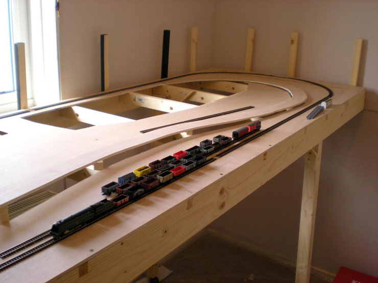
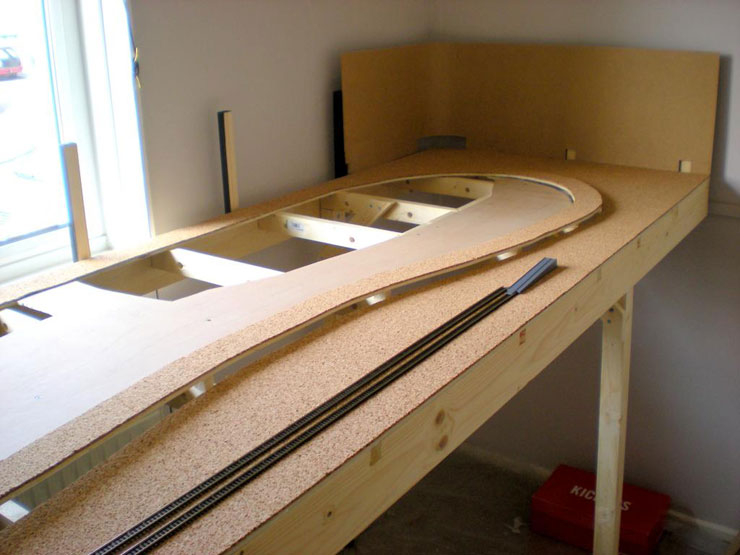
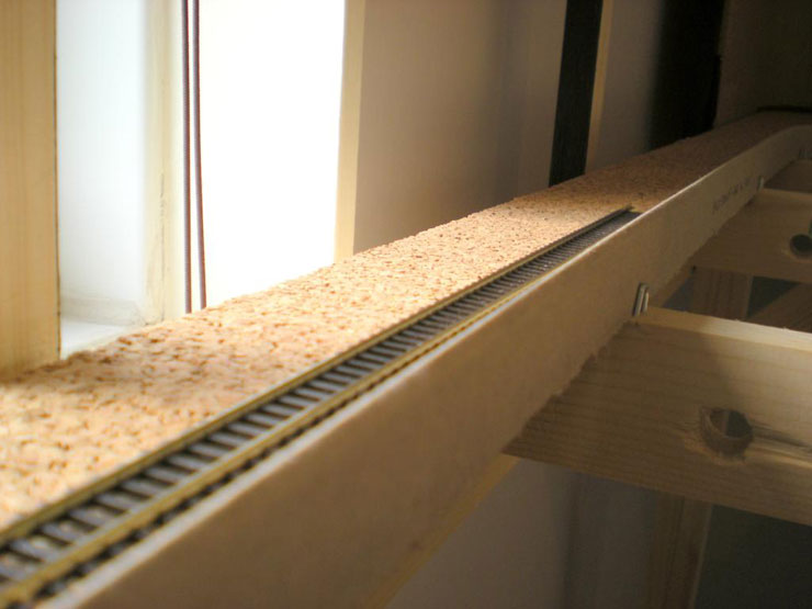
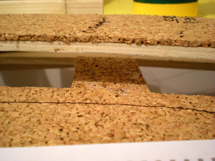
A bit more progress... Cork has been laid (under
just about all railway-related books, several planks, three 5L tins
of unused paint, and the timber for the fiddle yard traverser to
weigh it down), and the first shot shows the semi-fitted first part
of the backscene, which simply slots into place.
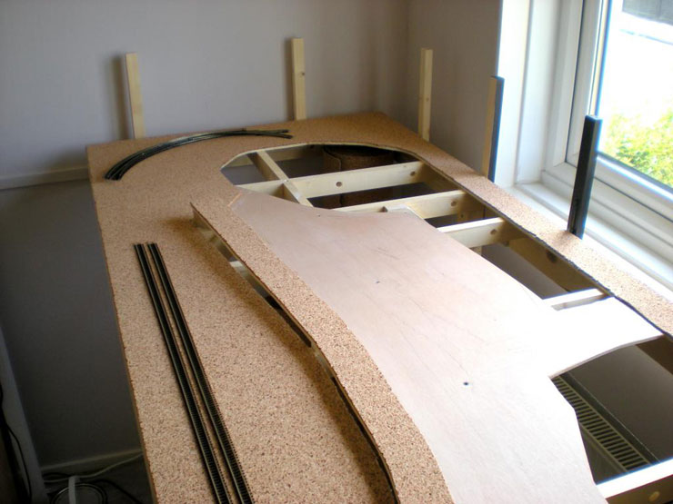
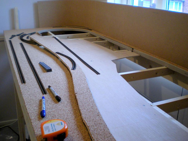
The cut-out areas of baseboard have been cut out of
the cork, as has the scenic area in the middle. Actually, there's a
lot more scenic area than expected. Hopefully the upper level will
eat up some of it. The rest will be formed of the yard next to
Branskome MPD and the street that ran alongside Bournemouth West
Station.
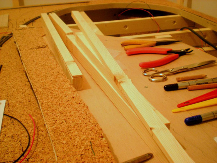
Today, from Poundland, I bought some cheap
double-sided sticky tape (the expensive stuff is just too sticky)
for sticking down the track prior to ballasting, and some
fine-tipped marker pens for marking out where the track will go.
Almost there with some permanent, live track...
12 September 2014
Slowly (oh so slowly) getting there... A simple
retaining tool for a removable protective barrier:
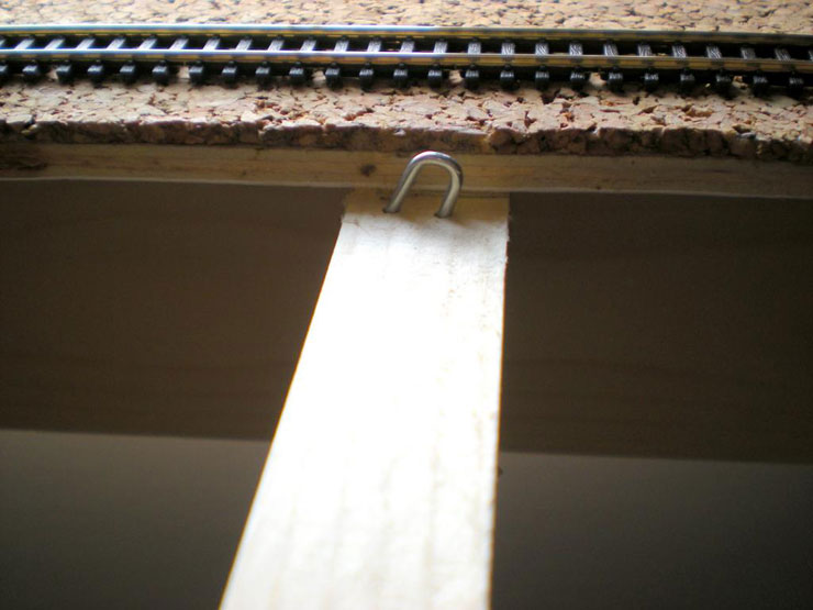
Providing that protective barrier for the hidden
back straight to avoid locos and trains plunging to a fiery death in
the gaping chasm below:
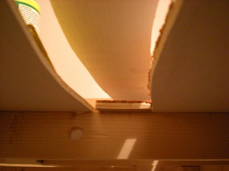
The finished backscene. Don't worry about the
corner gaps as they'll be hidden by the upper level. To be honest,
Flexi-MDF is a nightmare to work with. You'd be better off going for
something much thinner, lighter, less flexi, and just add your
curved corners with a flat piece of (diagonal) board or a thick card
insert:
The gap at the far end is for the final piece of
backscene which will fill the span between there and the start of
the fiddle yard (still to be built):
Now onto trying to secure the first pieces of track
(a minefield for the nervous beginner in itself!). I have Copydex
and I also have double-sided sticky tape. The latter has been
advised because it makes it easy to reposition the track, but I've
also been warned against it because it will degrade and jeopardise
future track stability. I've also been advised about hot glue (a
tube of Bostick left in the sun for too long?), but I'm guessing
that my best option is probably the Copydex.
Also, where exactly would you drill a hole next to
a set of points for a Seep point rod. Does anyone have any diagrams
or photos for an idiot? How do you mark out where the hole goes for
the power feed for Electrofrog points (the extra silver wires that
are attached to slips and 3-ways) while the point itself is sitting
over the potential hole? All these questions and more will never be
answered unless you dive in and sound off.
12 September 2014
This, adapted from a post on a forum, also sees to
cover points motor installation in pretty good detail:
-
Lay the track. Decide which side you want the
point motor connected to
-
Use a sharp pencil or pen, place it through
the tie bar hole to draw where the arm will go. Do this for each of
the tie bar's positions
-
Remove the point, and join up the two little
lines
-
Use a 1.5mm or 2mm drill bit and drill out
the entire length of the line. This leaves a slot under the tie bar
-
Clean up the hole and offer up the point to
it in order to make sure that it lines up
-
Glue down the point (Copydex in my case)
-
On the underside of the board, draw a long
line extending out of the ends of the slot, along the middle,
indicating the slot angle
-
Once the glue has set, offer up the point
motor, and mark off the length of the arm, and then cut it down
-
Take three bits of cardboard (about 1.5mm
thick) and wedge two of these on the outside of the point blades,
in order to centre them. The third piece is cut to the gap in between
the electromagnets on the motor. A slot is cut in the middle to again
centre the point motor
-
Insert the motor, and align the central rod
with the line drawn earlier
-
Screw it into place. Remove the bits of card,
and most of your motors should be pretty well centralised
That seems to cover most of it, plus making sure you
widen the tie-bar hole and mount the Seep on small blocks under the
baseboard. I do think the cork underlay was a good idea. It does seem
to do quite a bit of sound-deadening so far, and of course it gives you
a bit of lee-way with errors in drilling.
20 September 2014
Things were going pretty slowly until Thursday's
pinning down and bug-fixing day. If I had known just how difficult
Code 55 flexitrack was going to be with anything other than straight
sections then I might have been tempted to stick with Code 80. Never
mind, it's getting there, and Code 55 does look better.
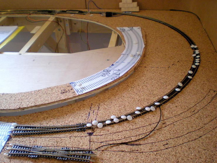
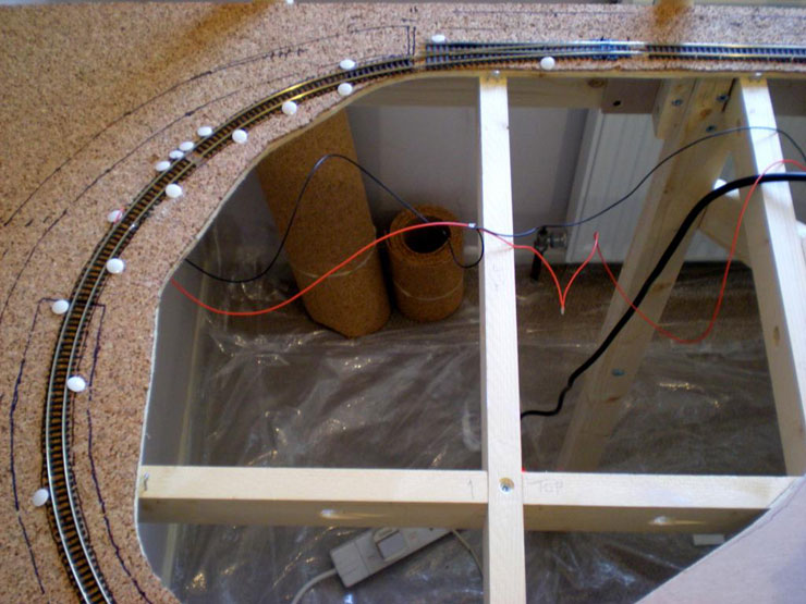
To start with, pinning down a tricky curve prior to
dripping diluted PVA between the sleepers to hold it down (there was
no way I was going to lift this to apply Copydex):
Complex height measurements for the incline
supports and bridge:
The engineer's train, for testing purposes. A
long-wheelbase loco like an 8F is ideal for testing curves. If that
doesn't get stuck on a curve that's too tight, pretty much nothing
else will:
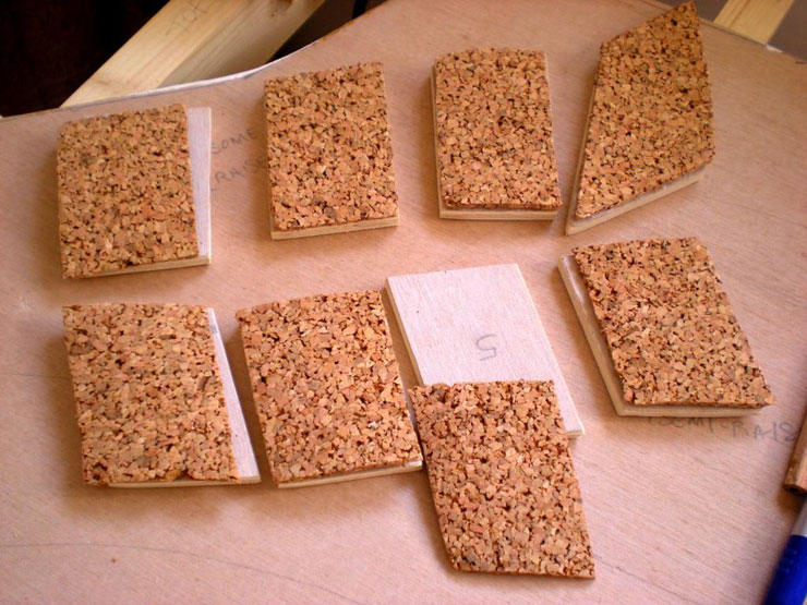
Support pads to go onto the exposed battens under
the incline so that the space can be brought up to surface level:
Another, even more tricky curve. This one proved to
be such an unhelpful so-and-so that the junction has been nicknamed
Unfriendly Junction:
One of eight support pads glued into place:
The view from the depths:
The incline support - essentially one single strip
of wood for the most part, cut with a finely-measured slope to it,
and then cut again into three or four pieces so that each piece will
sit on a support pad and the next piece can start alongside it (this
is so that it can cope with a snake-like curvy incline). The next
job is to test these in position before gluing:
The incline has already been tested in rough terms.
All sorts of tank engines made it up there with enthusiasm to spare
and hauling three Farish suburban coaches - all except the infamous
Dapol M7. That's going to need some extra weight added, although
perhaps the incline will be a little more gentle once I have the
proper supports in place.
20 September 2014
The continuous loop is close to being finished, but
the curve coming out of Unfriendly Junction may need to be relaid
first. Then there's just the station straight to connect and some
jury-rigged electrical feeds to put in place to bypass the isolated
sections, and the playing
testing can begin.
27 September 2014
Progress report.
The incline support 'post' has been cut to shape
and put in place, and a more serious test of locos was held. With
three suburbans, the BachFar Jinty made it up okay but visibly eased
off (realistically, of course). The Dapol Terrier motored up quite
nicely at low speed. Best of all, the Dapol M7 cruised up, with a
little bit of a slow-down where it crossed from the curve onto the
straight (two different pieces of track). Still realistic, as far as
I can see as the real thing was unlikely to hit a 1-in-63 slope
without some slowing down. The point is that it didn't struggle and
didn't sit on the spot, wheel-spinning. The incline works!
First part of incline support glued in place and
weighted, and with a spirit level across it to ensure that it's
entirely level. Plus the fiddle yard section has had its frame cut
out, glued and screwed (it's upside down in this photo):
I've also started to complete the running loop with
the last few sections of track on the northern side of EJ. Hopefully
can complete that tomorrow.
28 September 2014
Today's work was all structural:
The ply for the fiddle yard base was cut out, given
a coat of white ceiling paint on the underside, and glued and nailed
into position (I've run out of small screws).
The ply for the upper level on the main board was
cut out, and given a coat of white paint (and is now littering my
hallway while it dries).
The rest of the backscene panels were given an
undercoat (yep, you've guessed it - white).
The backing panel for the fiddle yard was cut out,
along with three shelving strips for extra rolling stock, and two
more pieces of support 'post' for the incline were glued into place.
Nothing much worth photographing, though, but it
will help the general layout look better eventually.
|