|
20 April 2015
Not much to report since January, sadly. It's been
another one of those 'long gaps between anything happening' which
seem to be besetting this layout. Partially that's because I don't
know half of what I'm doing and have to work it out from scratch for
each stage.
However, I have to admit that I lost heart for
a while, thanks to a series of problems that all happened at the
same time. That always seems to be the way, although it's more
usually one problem that rumbles on until it can team up with
another.
But I've been making small steps of progress again
recently, keeping entirely to one main job at a time.
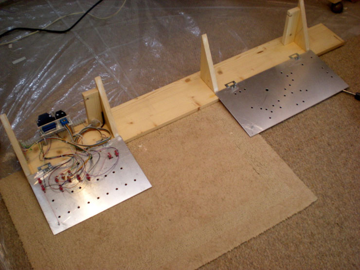
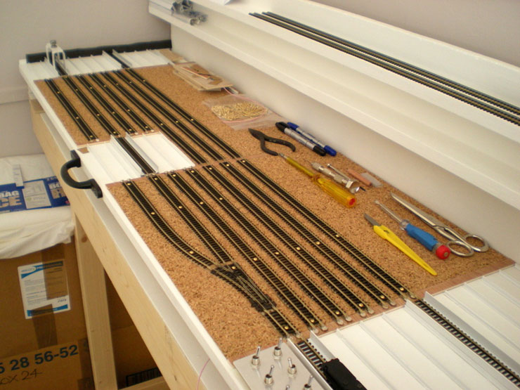
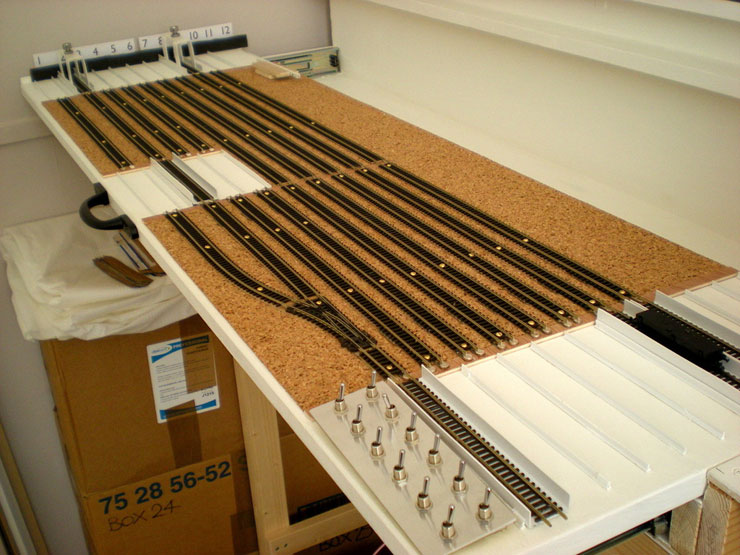
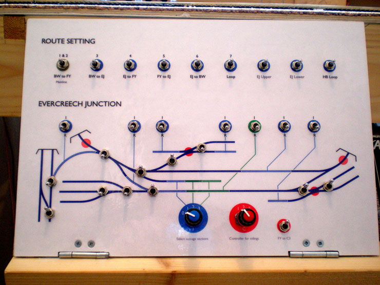
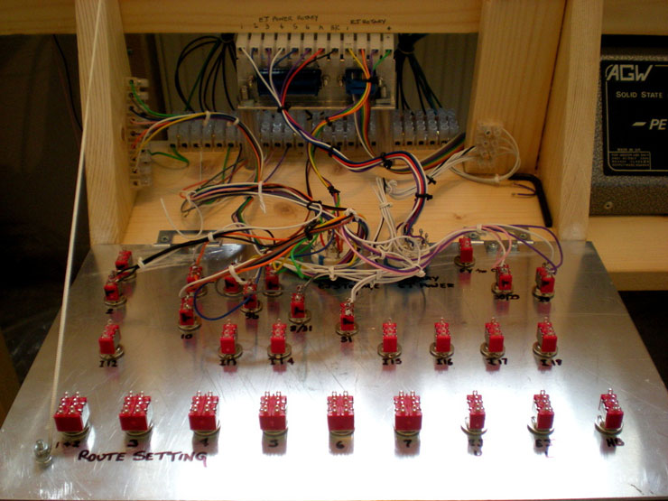
That one main job will be printing the mimic panels
and laminating them, and here's what they will be glued to, the
aluminium control panels behind which will be a lot of wiring that'll
control all of the points, isolating circuits, and several controller
options:
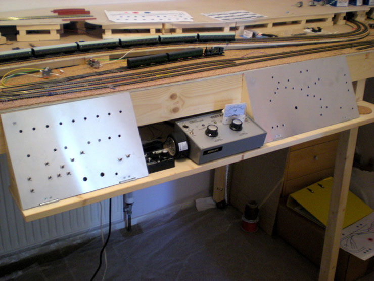
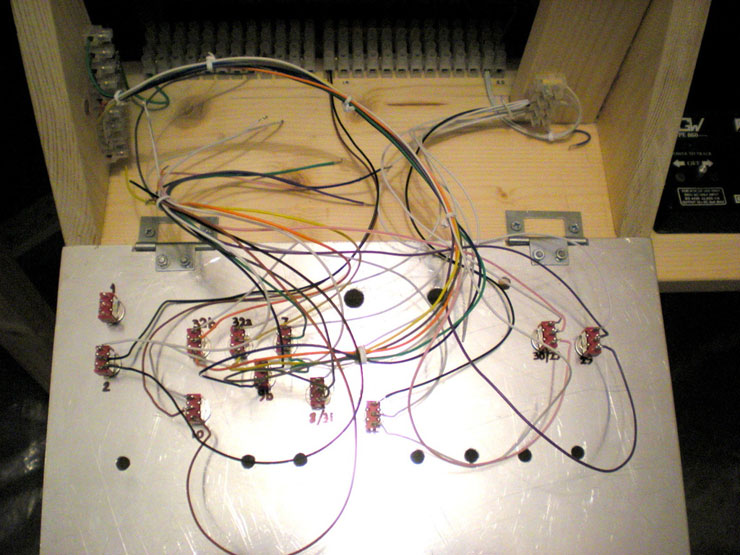
The left-hand one controls the front and lower section,
and this is the one that has the beginnings of wiring:
More news when it arrives...
20 April 2015
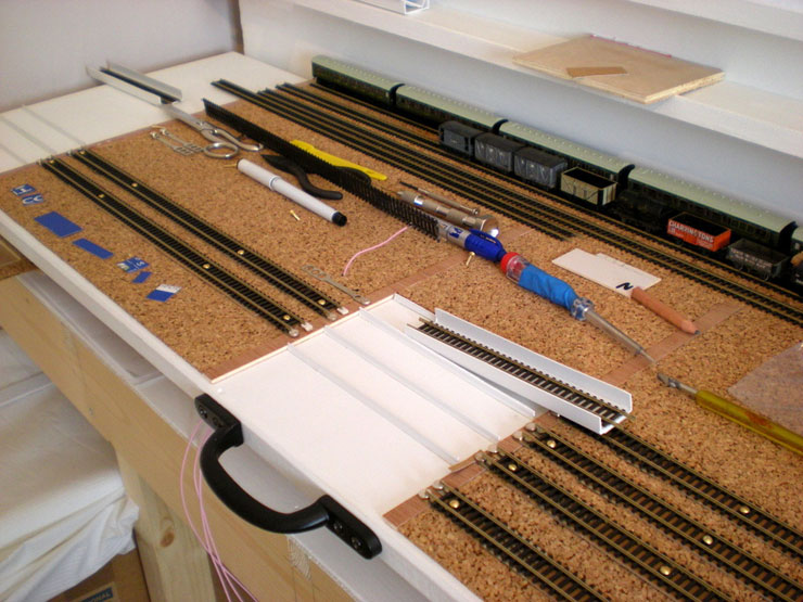
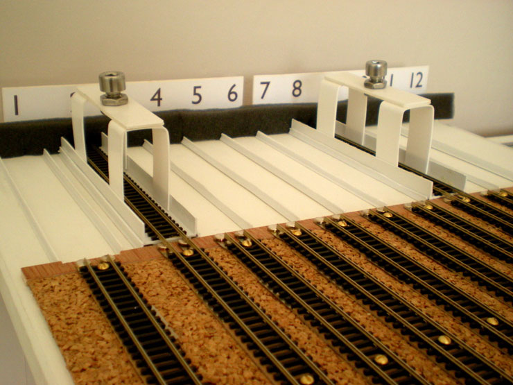
I haven't had the courage to test my cross-board
track for its 'ping' yet, even though I have the razor saw! I've
also added some extra protection in the form of drawing pins with
the 'hood' removed, rammed in along the outside edge of the outside
track. Ballasting will largely hide them, but any help here in
holding the track in place could be vital.
21 June 2015
It's about time I updated this. Progress has been
slow, mostly because I've been waiting and wanting to get the mimic
panel printed and laminated before adding any more switches to the
control panel.
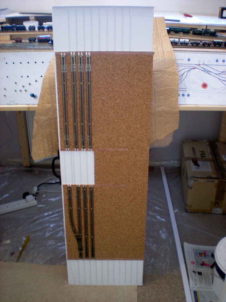
The baseboard join has been suitable strengthened
(I had quite a bit of more experienced help), and it looks good for
cutting now:
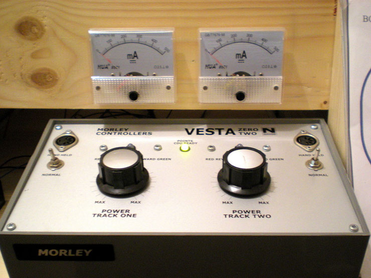
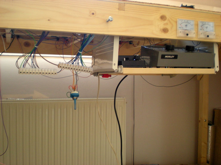
I've also installed the two amp meters above their
respective control dials:
I've been working on the fiddle yard traverser
entry this weekend, trying to solve the power transfer problems from
fiddle yard entrance across the removable cartridges. I think I
might just have done it. Photos to follow shortly...
8 July 2015
Progress update... although nothing dramatic. The
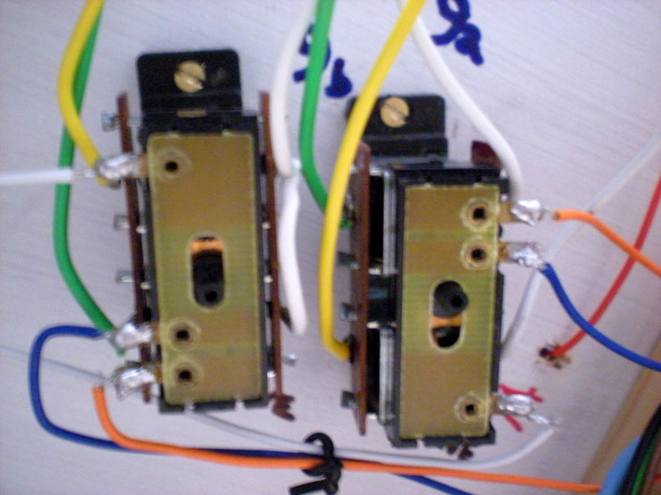
first SPDT switches have gone in under the Peco points, and I'm not
especially impressed so far:
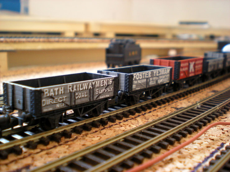
A bit of a diversion was a first order of Robbie's
Rolling Stock wagons to arrive. They'll need suitable weathering and
coal loads:
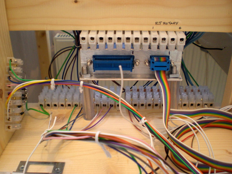
The detachable control unit was detached for a new
installation...
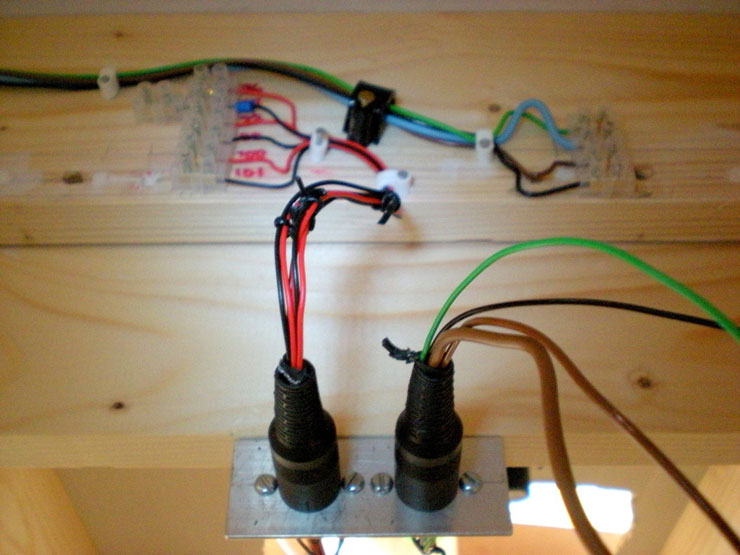
...but it allows me to show you the layout side of
the pull-aparts. Ignore the hanging rotary switch. That hasn't been
fully installed yet:
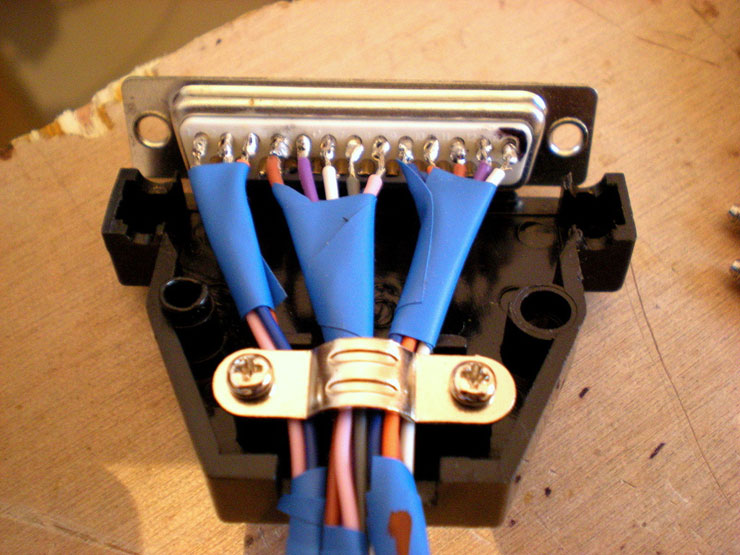
The new installation are two D-plugs, a 9-way on
the right and a 25-way on the left, supported by a metal bracket
which is bolted through the base of the control panel and held up
by an off-cut of rubber hose (fish tank variety):
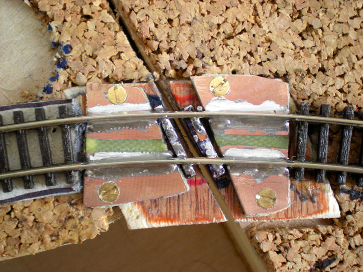
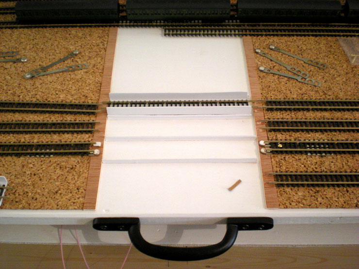
Another progress point has been supplying
electricity to the traverser tray. These 'springies' have been cut
and folded so that the tail (right) connects to the underside of the
track and carries power to the 'bouncy' connectors (left):
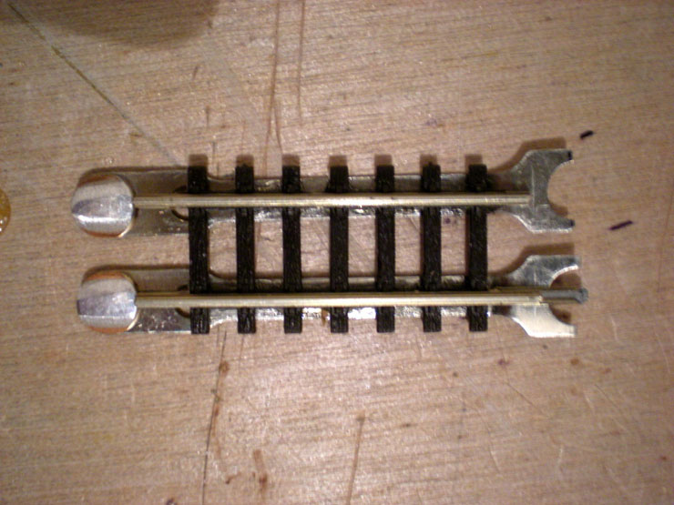
Underside view:
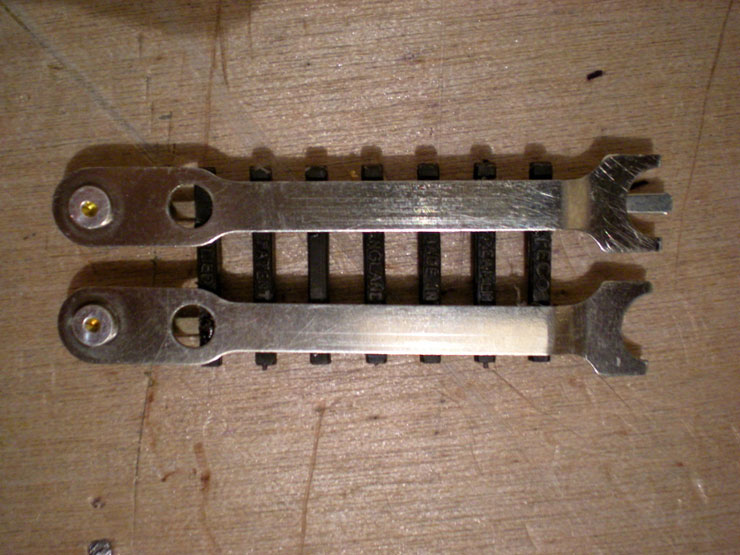
In position. You can see that the cartridge sits on
top of the springies, improving connectivity to around a 95% success
rate:
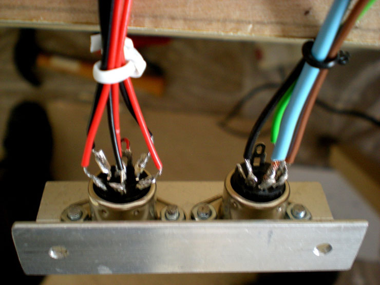
Then I tried using DINs to provide connectivity
across the main board-fiddle yard connection. This side was easy to
solder, but the other side was a nightmare:
And my soldering was never great, so after a few
problems (possibly due to dry joints) I replaced the DINs with
pull-aparts:
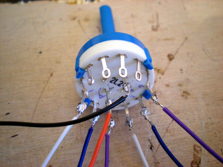
Next job was properly wiring up the rotary switch
to the small control panel... with some signature dodgy soldering:
That was installed successfully, but you'll have to
wait for the next batch of photos to see it...
17 July 2015
Things have been progressing lately so it's already
time for another minor update, approximately one year after
construction on the layout first started.
First there was the Mk1 cartridge for use on the
fiddle yard's traverser tray. This version remains in use as it's a
handy tool for instances in which turning locos is not required, and
you just want to bridge the gap or conduct electrical connectivity
tests:
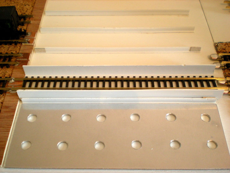
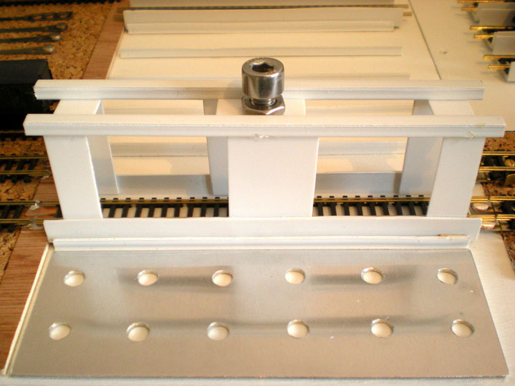
Then there was the Mk2 cartridge, with a circular
bolt to make it easy to pick them up and swivel them 180 degrees
while transporting the loco to the other end of a train. It was a
clunky, ugly mess that needed lots of pre-cut panels of plasticard:
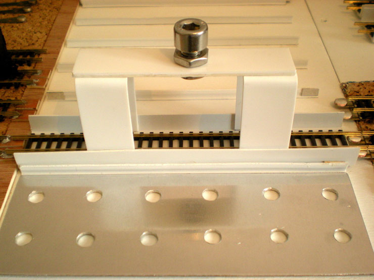
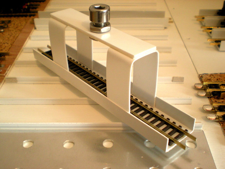
But then came heat-moulded plasticard, a shape that
could be formed of one single piece of plasticard (repeated at the
other end of the cartridge), and a single panel on top held in place
by super-strong car registration plate double-sided stickies, plus
the old 'swivel bolt'. The Mk3 cartridge was born:
Actually, it could also be called the Mk3 travel
machine, which means that it will go on to conquer the universe and
exterminate all who are not like it, but it will also start this
path to supreme power by exterminating its creator. Hmm...
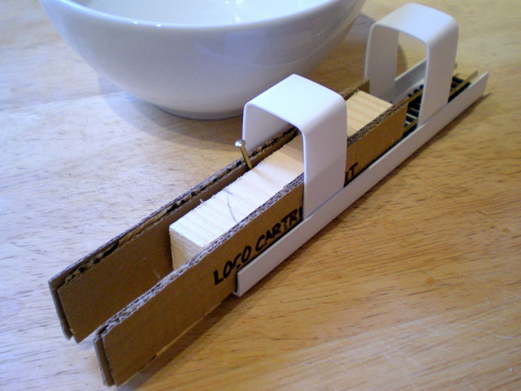
Anyway, cartridge problem solved. I already have
four working examples in operation and they seem to do the trick
very nicely. They're also very easy to build. Every time I make a
cuppa, I add some of the water to a bowl and form another strip of
plasticard around a simple wooden former. A couple of dunks, a
couple of bends, a couple of splashes under the cold tap, and I have
another folded strip that's ready to glue into place. Easy.
15 August 2015
Update time.
Soldering to a 9-way D-plug. Not as difficult as it
would have been a few months ago:
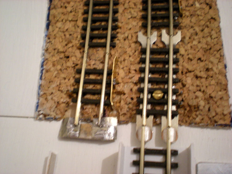
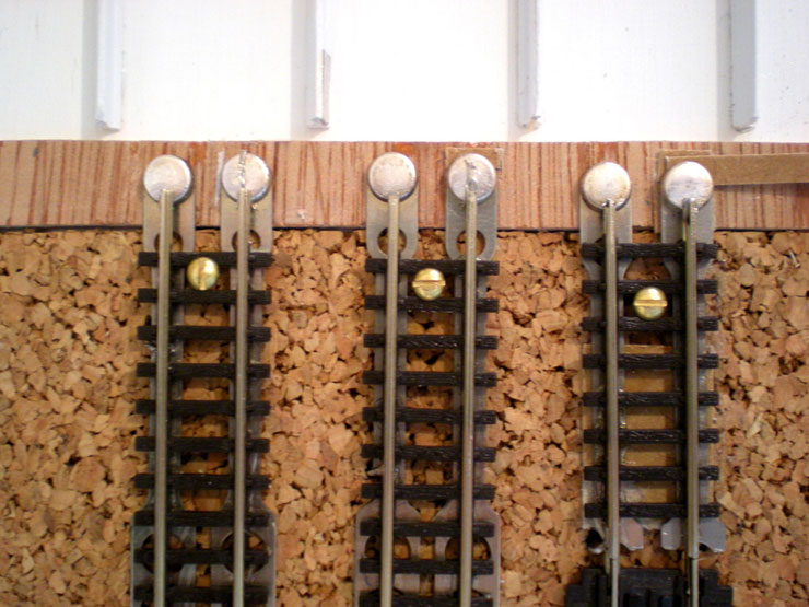
Reinstalling the first fiddle yard storage road
with new contacts where the track meets the cartridge points:
Electrical contact across the cartridges is now
around 95% reliable:
Four roads with front halves completed, plus two
back halves. The track is now held in place with screws so that it
can be removed, realigned or anything else:
Fiddle yard traverser tray removed for essential
maintenance...
...which includes installing a wall at the far end
of the storage roads...
...and formalising the isolator/feed wiring
underneath the tray (plus a bit of paint repair work):
A day later and the tray is back in place, complete
with 'bumper' black foam laid over the far wall, more cartridge
slots in place, and a total of seven storage roads in place (but I'm
running out of track):
Isolator control panel for the fiddle yard, not yet
wired up (except for Road 2) or fully fitted:
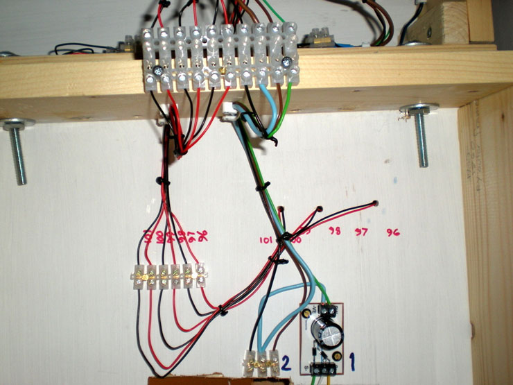
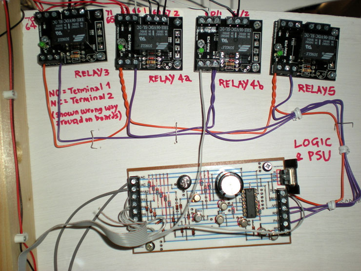
The last job for today was completing the logic &
PSU board wiring under the main layout. This will help with firing
points as part of route setting and switching controllers to certain
sections of the layout:
More next time.
1 September 2015
Update time.
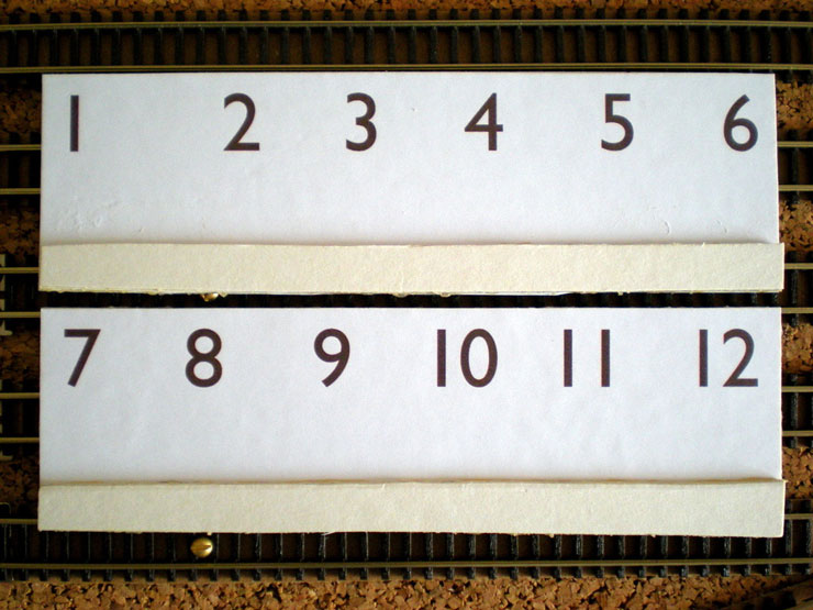
Progress over the last week or so has been good.
Firstly, the fiddle yard's storage roads need to be numbered to tie
in with the isolating circuits. Two layers of cereal box overlaid
with printed numbers in Gill Sans:
Numbers fitted at the far end of the fiddle yard,
along with some anti-crash foam over a wooden backing strip. I've
also finished relaying the existing storage roads and used up all my
remaining track. The last three roads may have to wait some time...
A close-up, with two loco cartridges in place:
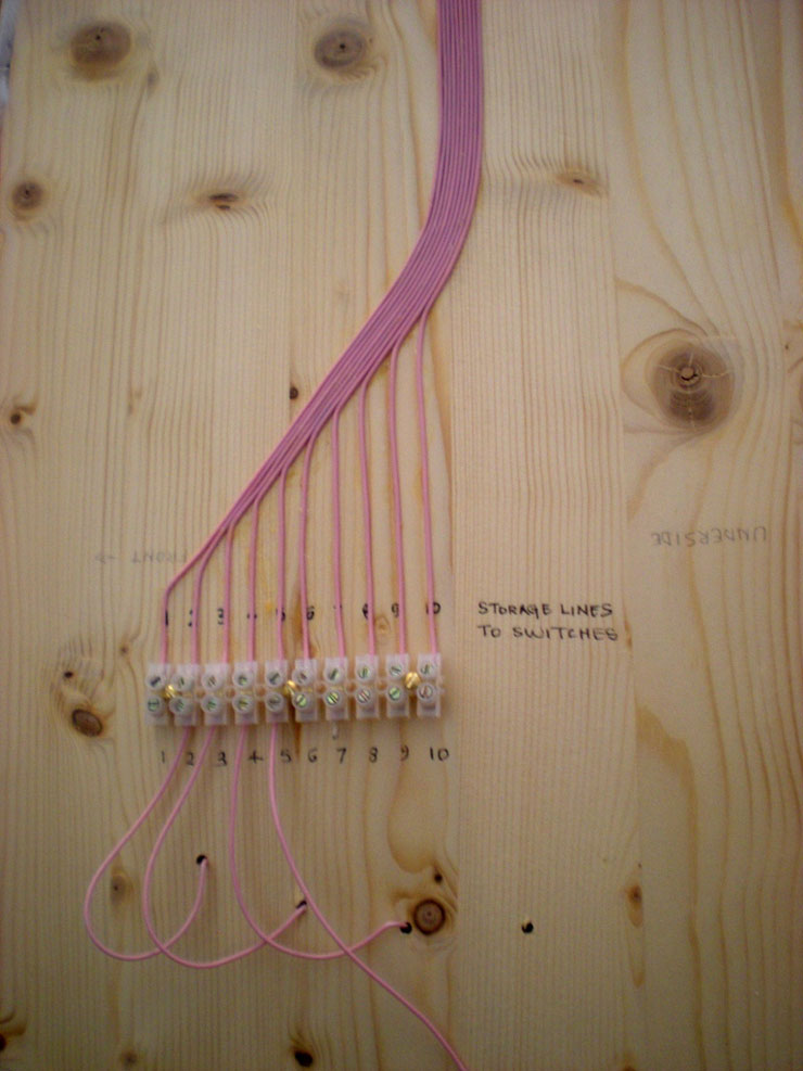
Wiring the isolating switches (you can see where
the panel sits in the photo of the whole fiddle yard, above):
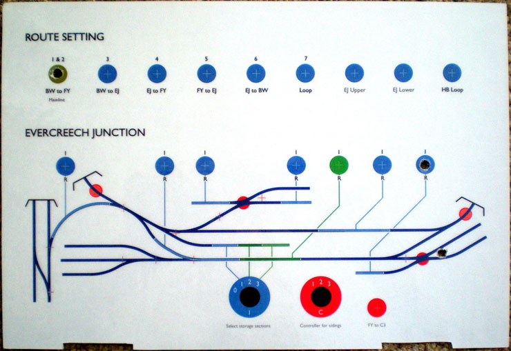
And now for an even bigger step forwards - the
first mimic panel which will house controls for the lower level on
the main board. A local place laminated it for the acceptable price
of £2.99, and there are three holes drilled already:
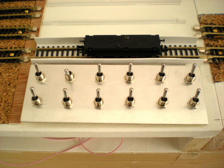
And here it is, glued onto the aluminium panel and
with all switches fitted (but not all yet wired in or working):
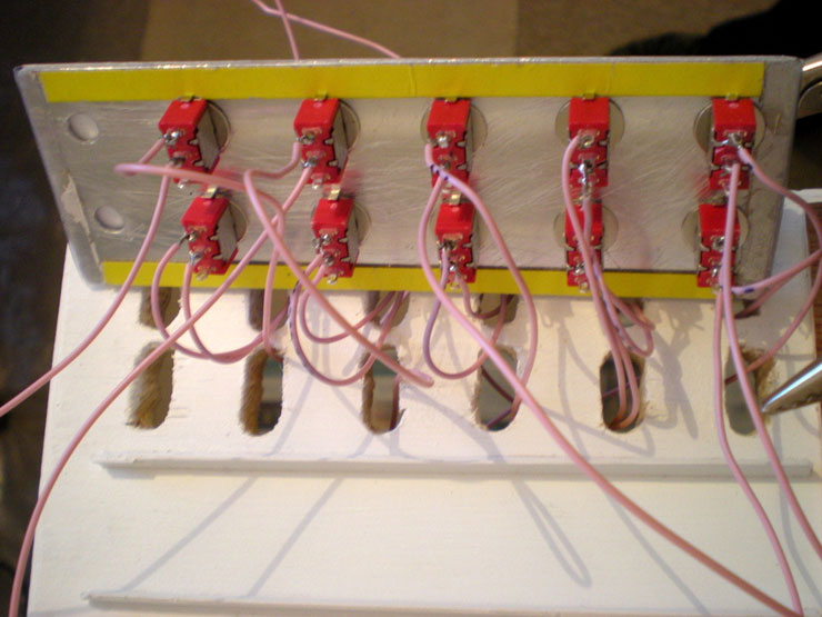
The insides, with points switches largely wired in,
isolator switches next to get that treatment (in the middle), and
route-setting switches (nearest the camera) still a total mystery:
If I carry on making progress like this I'm in
severe danger of running out of jobs that will help me to avoid
working on the points motors...
2 September 2015
The traverser brought with it a series of problems
that I've slowly been solving along the way, but it's working better
and better all the time now.
One last 'big step' to work out is a locking
mechanism to keep it in place when it's aligned with the exit.
There's very little space for any of the traditional methods. I was
initially going to use Bales catches underneath the tray but was
advised that that would require too much 'pull' to move the tray -
with the risk that the stock would be sent flying in the process.
Plus I need more track of course! The cable ties thing is easy. Just
save up lots of them and then cut off sections for regular use. I'm
almost out of them now, but since that shot was taken I've added the
isolator wiring and even more cable ties!
|