|
5 October 2014
The latest news is that there's not much to show.
This layout-building process seems to be a mix of frantic activity
and long periods of waiting for the next stage to happen. In those
gaps I'm usually busy on the
Grouping Workbench
modelling work, so it's not actually time being wasted.
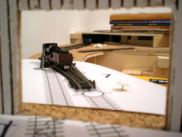
On the plus side, the lower level loop has been
completed (cue 'playing trains' just a little - which is entirely
for testing reasons, naturally). Getting that completed was a major
step forwards, but it wasn't all plain sailing. Working with Peco
flexitrack involves a bit of a learning curve.
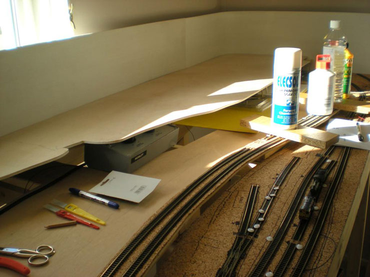
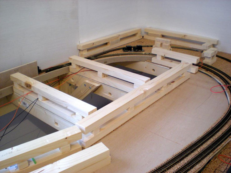
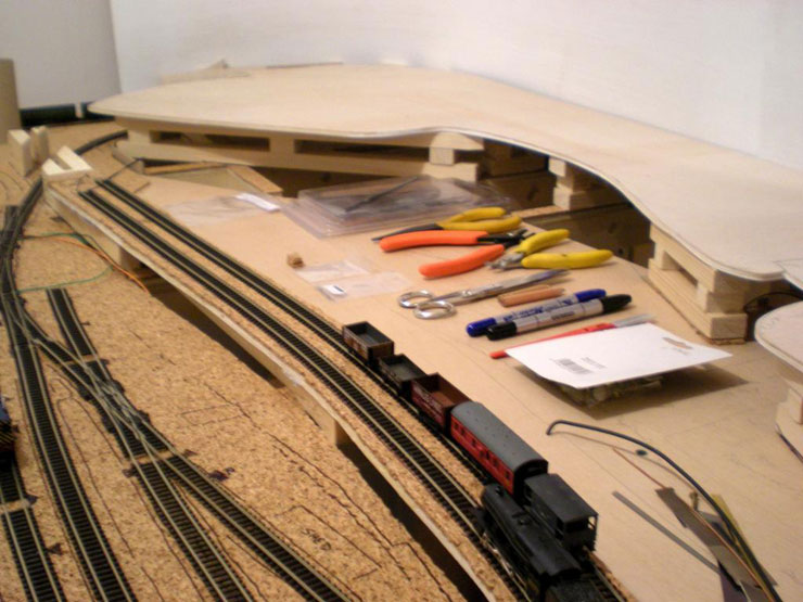
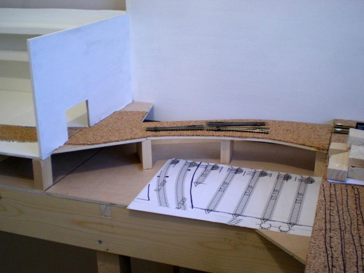
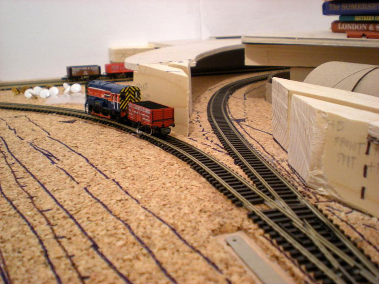
Track laying continues at the front of the layout
(the Evercreech Junction Station area) and at the start of the
incline which begins in what will be a tunnel area, so it's
important to get the transition from flat to incline just right.
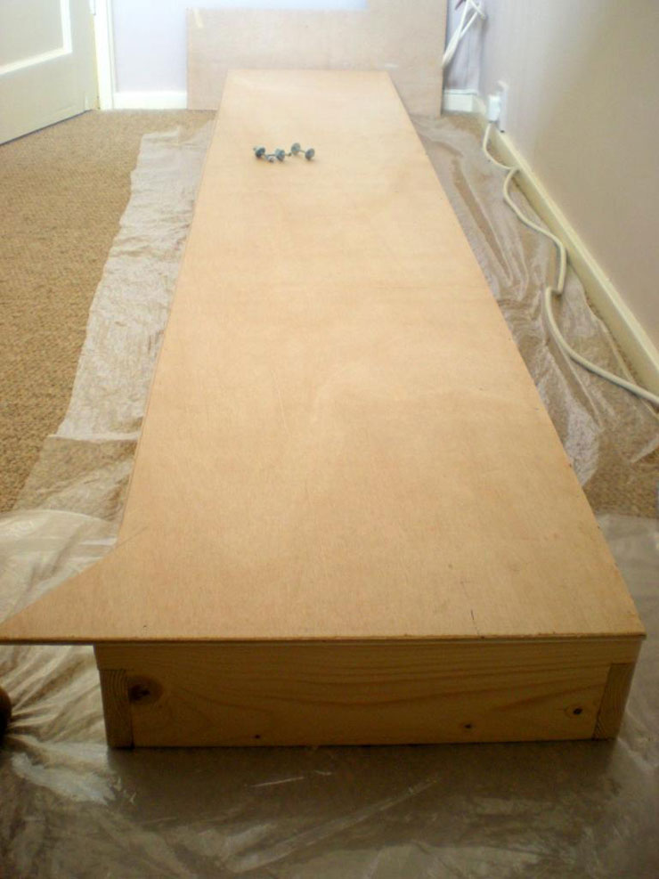
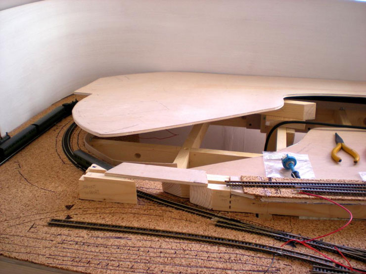
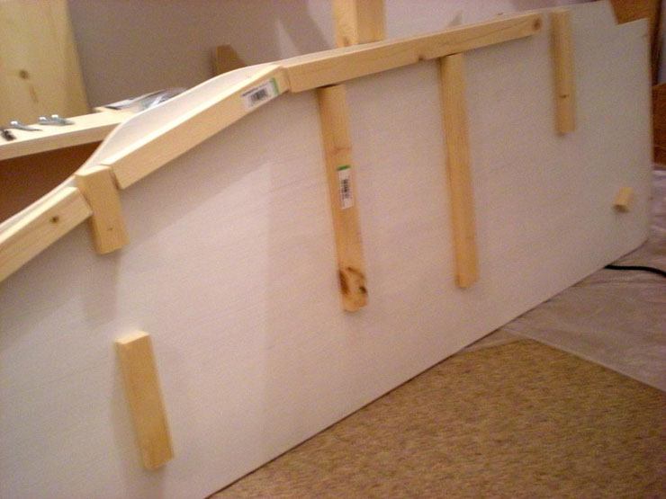
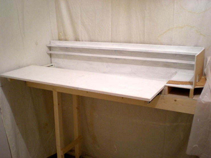
The frame for the fiddle yard unit has been topped
with 6mm plywood and is now ready to get some legs:
...and the backing panel has been secured:
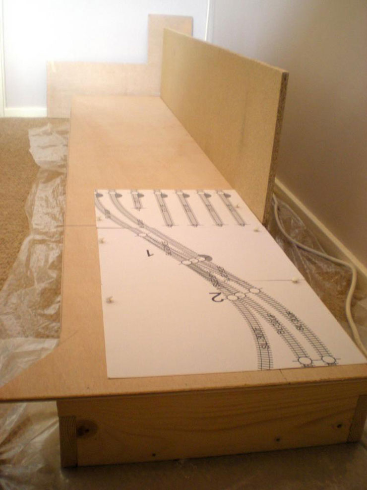
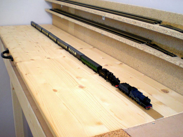
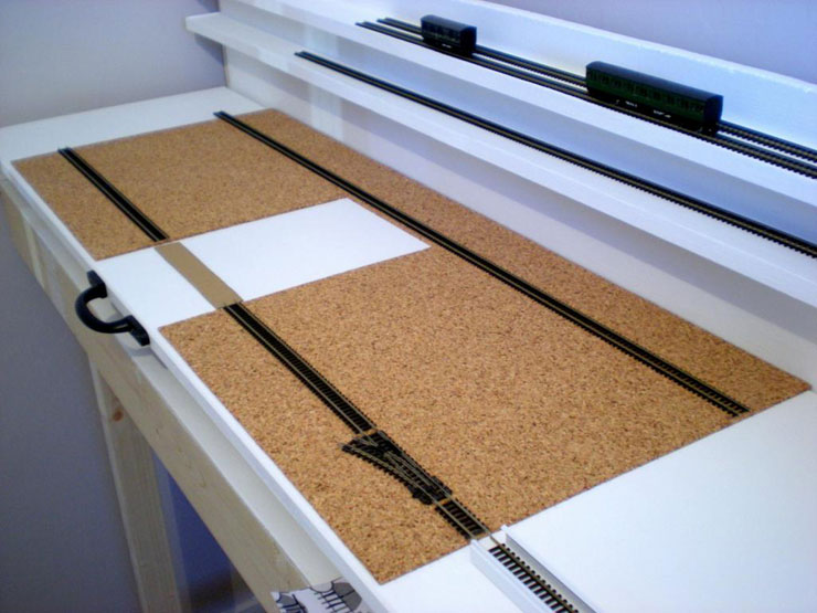
This shows the full length of the fiddle yard beyond
the scenic break. It takes up much of this unit, but that's because
the longest train will be a seven coach double-headed express. This
weekend's work also included sawing timber for the traverser tray
and the controller tray, working out which points to link to the
first two relays, and how to wire up the banking loco parking
siding to a 3-way switch.
15 October 2014
Another update:
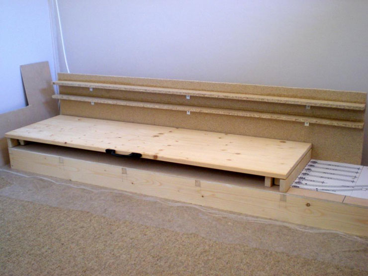
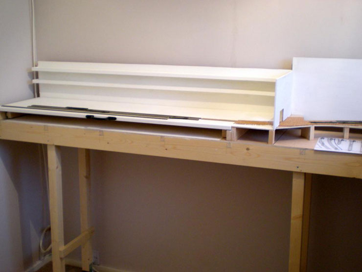
The shelving at the back of the fiddle yard has
been installed and is awaiting a coat of pain. The tray works
manually but still needs some kind of catch mechanism to be fitted.
I was going to use Bales catches based on Tank's huge fiddle yard,
but I've been strongly advised against that. Hmm...
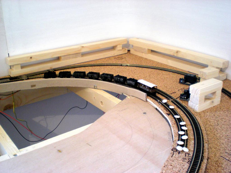
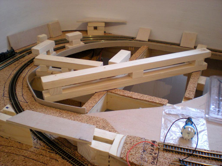
Laying track up the incline and positioning the
first support battens for the upper level:
Upper level test:
More support battens in place, but not yet secured:
Track base between fiddle yard traverser and main layout in place
but not secured:
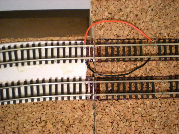
First official wiring completed:
19 October 2014
I've had a Jason Statham moment - Crank! Last
minute pre-construction adjustments to the track plan didn't
coincide with last minute adjustments to the baseboard plan, so at
least three points at the front of the layout clash with support
struts. That means some remote points operation is required, and for
that you need a crank: Crank No 1, set up for me by someone who
cares for idiots in the community:
Crank No 2 set up by the idiot in question!
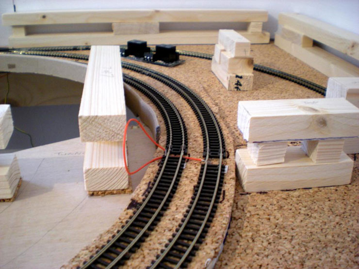
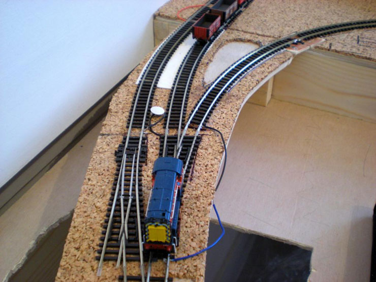
The second platform loop at the front has been cut,
laid, glued and wired (temporarily). It works, but due to the
three-way point at the far end it can't be used regularly for now:
Next stage is to try and complete the upper level
general construction work and start connecting up power feeds on a
more permanent basis...
28 October 2014
Another quick update. The removable upper level is
in place, with two dowels at each end to locate it when slotting it
in, and the goods siding at EJ has been laid (with another crank for
half the double slip):
Now the incline curve has to be completed:
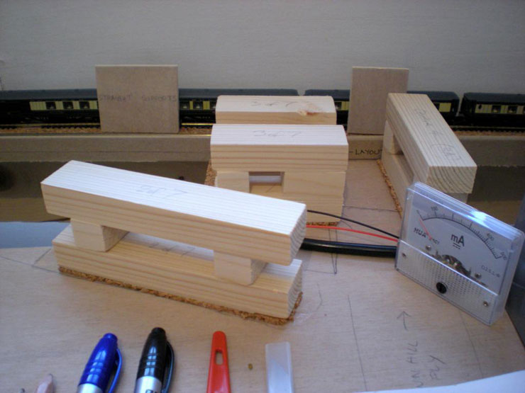
Some support battens under the upper level:
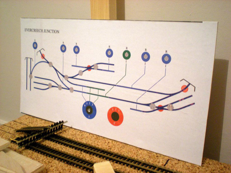
The temporary mimic panel for EJ (Lower Level):
In the meantime, work continues on the fiddle yard
section...
29 October 2014
I should provide a bit of clarification about the
upper level's support battens. The width-wise gaps are there to
allow for points motors. The big gap along the straight edge is due
to the fact that the lower level back straight runs directly
underneath and there isn't space for wooden battens. I'm working on
that, and this shot shows the first stage of that solution:
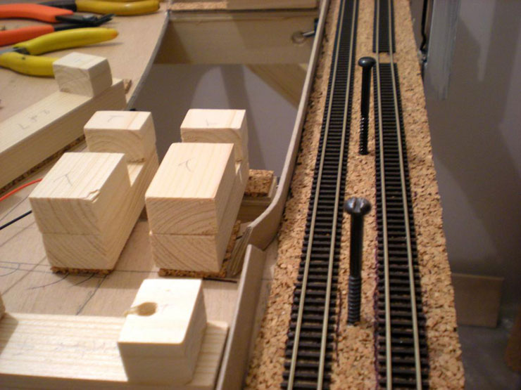
They're 60mm screws which are pretty solidly
anchored, so they don't move around at all. Luckily, the running
lines have a gap between them and nothing comes closer than about
3-4mm to any of the screws, not even the outside-framed Class 08.
Stay tuned...
6 November 2014
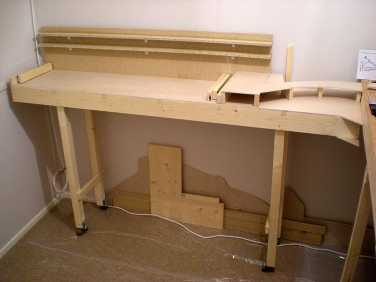
While I wait to get my hands on the extra supports
for the upper level, construction work has switched to the
detachable fiddle yard. The baseboard and frame were put together
some time ago (see photos, above), but the legs still needed to be
done, complete with wheels and adjustable legs:
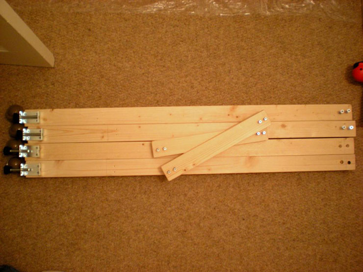
Admittedly, the adjustable legs should have been
fitted to the outside or inside of the legs, rather than behind
them. They tend to foul one set of wheels in the direction of
travel. Testing the positioning of the fiddle yard unit:
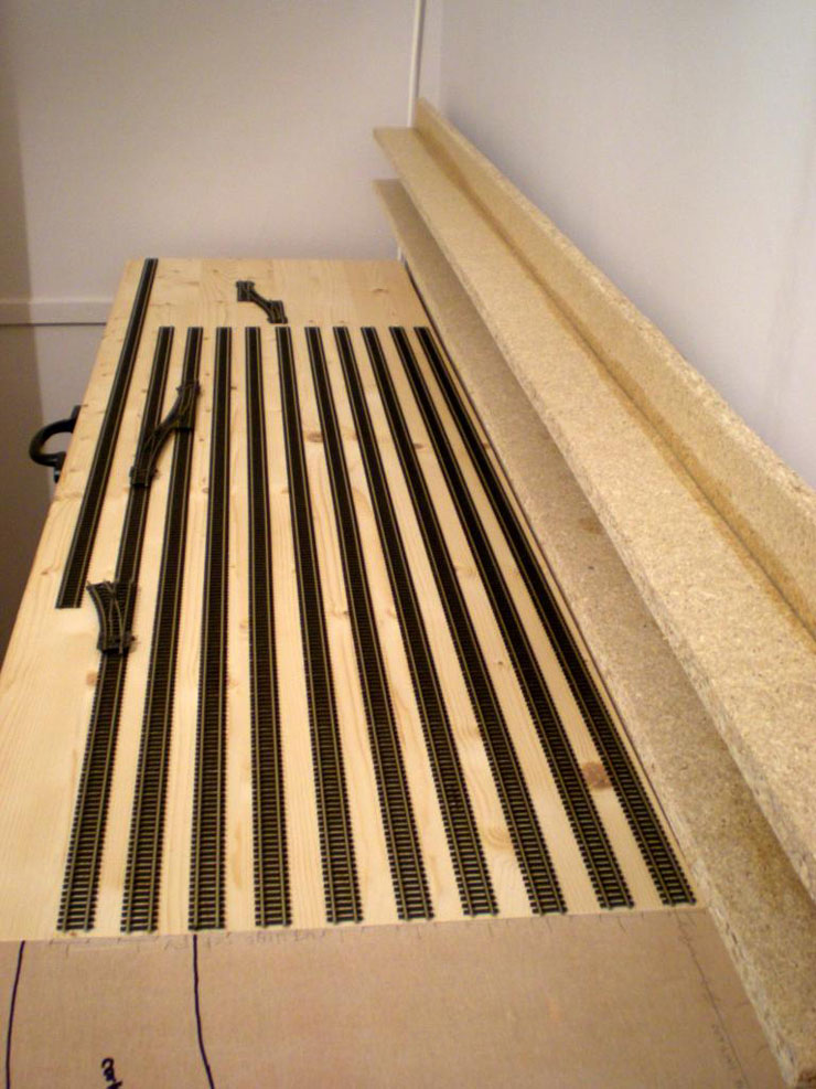
Testing how many storage lines I can reasonably
squeeze in (the answer is ten and three quarters):
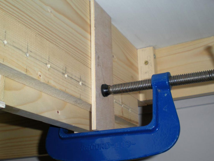
Clamping the fiddle yard unit to the main board in
preparation for drilling two bolt holes and four holes for locating
dowels (above the block with all the markings on it - that's a
left-over from an entirely different bit of work):
10 November 2014
Here's the latest update, although most of the work
recently has been preparation and not much progress. Testing the
traverser for train length. It can easily take seven coaches and a
double-header:
The piece of brown card is a tester for a cartridge
system. The plan is to have a cartridge at each end of each storage
line. Incoming trains run up to the end so that the loco is on the
cartridge, and then this can be lifted, turned, and placed at the
other end of the traverser, with an empty cartridge replacing it.
Any ideas for building the cartridges? I have 3mm ply to start
with...
The upper level was set to the correct height, but
when testing the last part of the incline (from the bridge to the
upper level joint), the climb seem to steepen for the final 20cm or
so. So the upper level has to come down a bit. Luckily, the support
battens are on a layer of 3mm cork, so this is coming out. Saving
3mm might be enough to make all the difference. It means ripping out
each support batten, scraping off the cork, and re-gluing the batten
in place. It can't be done all at once to avoid the dowels being in
the wrong place - much easier to do each half separately, and the
first half is now done:
One smelly undercoat on all the visible surfaces of
the fiddle yard. The next step, once it dries and the fumes clear,
will be to lightly sand it and then add two coats of leftover
ceiling paint:
20 November 2014
Just about got time for an update (work has been
manic for the past couple of weeks). The fiddle yard has received an
undercoat and four topcoats, and seems to be looking good:
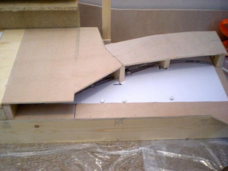
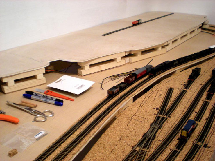
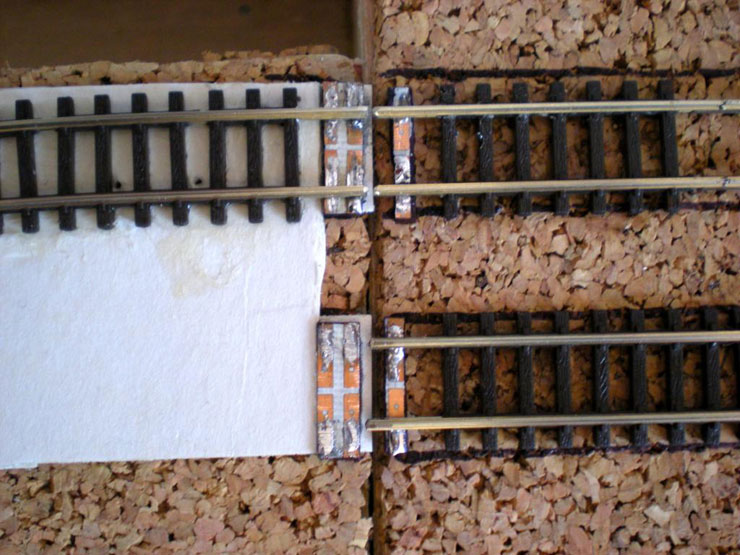
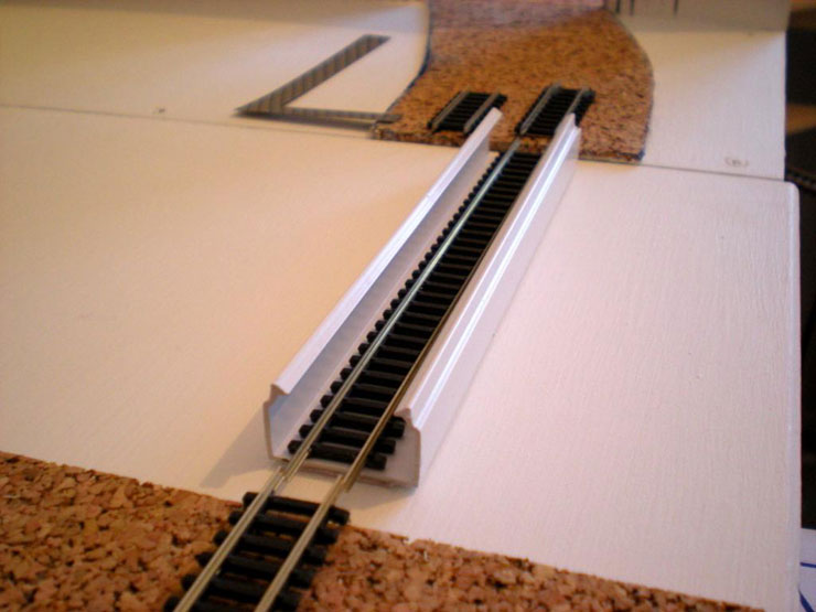
Now to bridge my first baseboard divide and get the
track extended onto the embankment:
Two glues to stick down the brass bits and one
soldering iron to secure the track to them... messily. I used
Minitrix rail joiners laid upside down on top of the rail head to
make sure the bridged section remained in line (Minitrix joiners are
bigger and wider than Peco Code 55 types), and then glued down and
pinned the curved track, wrestling it into place in about ten
minutes of work. Luckily the glue dries fairly slowly:
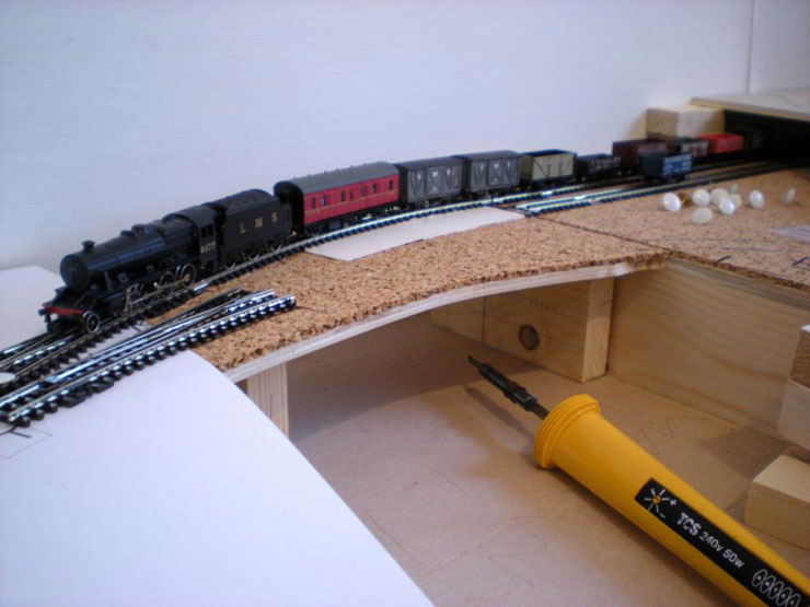
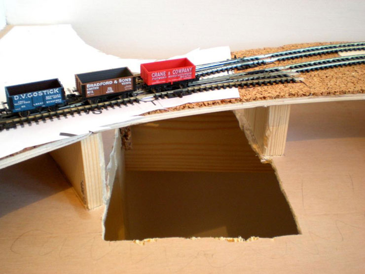
First over the gap - the engineering train headed
by the 8F and its long wheelbase:
Second track down and the brass bits masked with a
black marker pen. Once the ballast is down this should look okay:
The view from the fiddle yard:
Stay tuned for more...
10 December 2014
Not much done recently due to weight of work and
also a large number of new pages to prepare for publication on the
History
Files in just over a week, but here's the little progress that
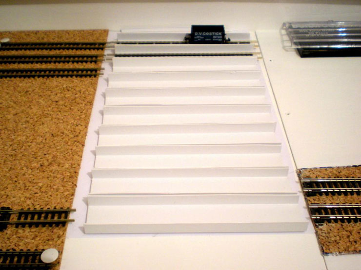
has been made. Cork laid across the traverser tray, allowing spaces
for loco cartridges. The three lines at the back will be for full
length trains, so a central cartridge won't be needed.
Here's the early prototype loco cartridge, simple
26mm cable trunking with self adhesive base. It needs to be raised
(so the self adhesive will come in useful):
And it suddenly dawned on me that there was no
access point for positioning points motors under the embankment.
Whoops. One hack and chop later. Mind the gap, lads...
17 December 2014
With the preparations under way for Christmas and
things at work winding up, I've had spots of time this week to do
little bits of work on the layout here and there. The Highbridge
Loop (aka short cut to the fiddle yard) has been laid and is open to
construction traffic only:
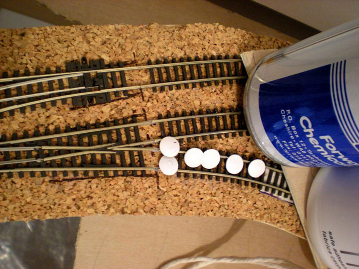
The other end of the loop crosses a baseboard joint
(cue the overuse of much solder to ensure the tracks don't ping in
opposite directions when they're cut next year), and joins a
junction at a fairly tight radius. It's never going to be used by
anything with a long wheelbase so that's fine. But it meant that
getting the end of the curve to align with a point fitted with IRJs
was a bit of a nightmare. Luckily, using Copydex the first time
allowed me a second bite of the cherry and the chance to get rough
with it. This time it's aligned and it'll stay that way:
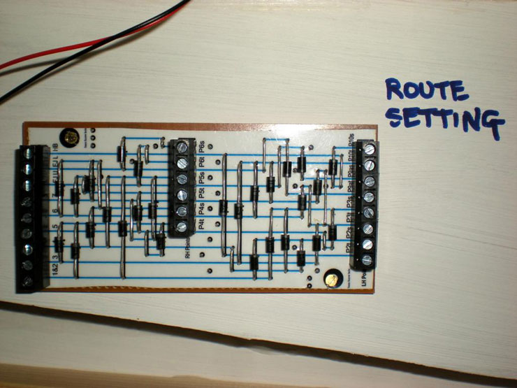
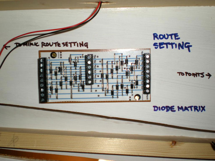
The diode matrix for route setting - fitted at
last!
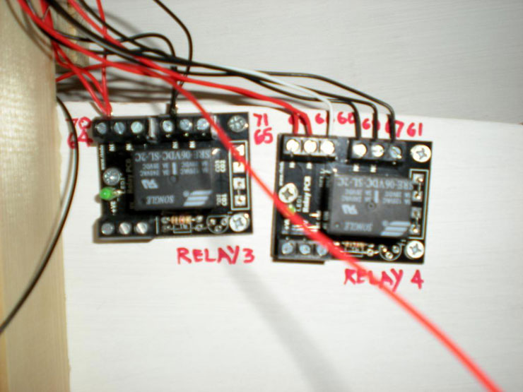
Relays fitted and wired in, although they aren't
operational yet:
More loco cartridge tests on the traverser. Results
encouraging:
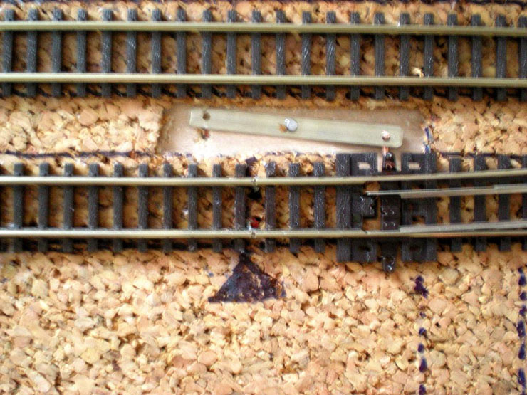
First points motor fitted but not operational. How
on earth are you supposed to test whether they've been properly
fitted...?
That's pretty much it. The Highbridge Loop is still
drying off so I won't be able to test that today. The loco
cartridges need a couple more cartridges to be fitted with track so
that I can test for misalignments. It looks unlikely that the first
loco will be able to make its way to the fiddle yard this year.
22 December 2014
I had a bit of a brainstorm in regard to the
traverser wiring and power connectivity and spent a furious half
hour scribbling down notes that will cover just about all of the
rest of the work. So the way ahead is clear. I just have to find the
time to do it.
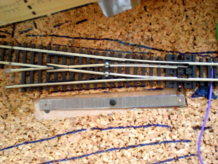
As for the points motor, I suppose I used something
similar, only less hardening - blu-tack! A small blob on each corner
of the mounting plate allows you to hold it quite easily in position
while you mark out the screw holes for pre-drilling and then secure
the motor itself. At the moment I still haven't been able to test
the motor so that I can be sure it's correctly mounted.
23 December 2014
Just time before Christmas for an update of the
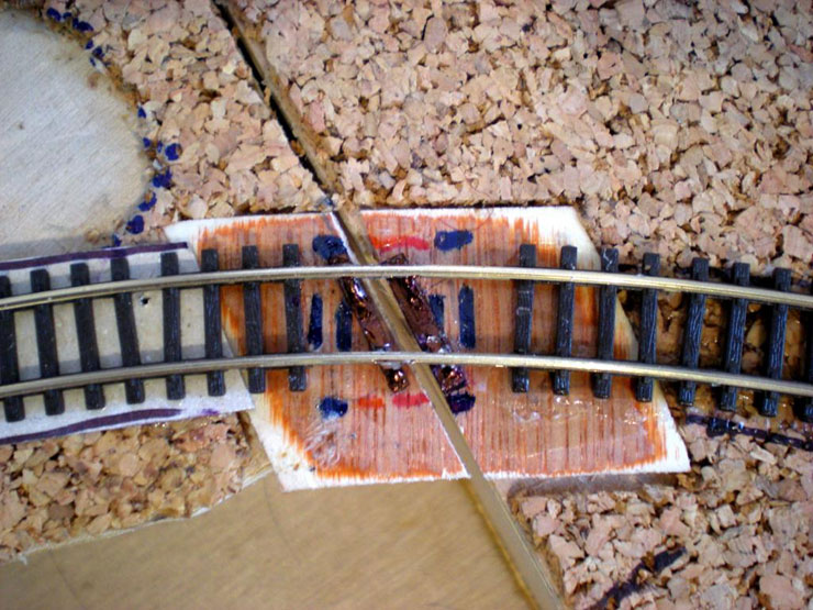
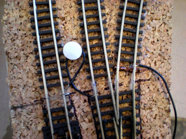
weekend's work. Firstly, an overview of the tricky junction. It
crosses a board joint and meets a junction (nearest the camera) at a
pretty tight angle (somewhere midway between R1 and R2, I think):
Where the track crosses the boards, it has been
soldered to PCB strips that are superglued to ply inserts in the
cork. The hope is that when I can get me a razor saw and cut the
rails, they won't go 'ping' and rearrange themselves into an
entirely new track configuration:
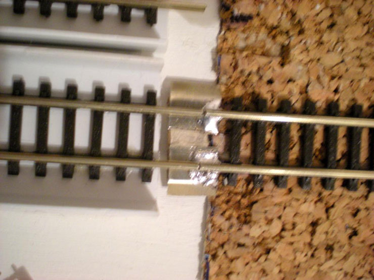
At the junction end it needed another strip of PCB,
temporary metal rail joiners until everything had set, and a
bucket-load of solder to cement it all in place:
And now attention turns to the soon-to-be-connected
fiddle yard. The loco cartridges are mostly ready for testing,
although they still need some work to complete them. The spacers are
being put in place to divide the cartridges, and these come from
off-cuts from the £1.56, two metre-long cabling duct, while the
cartridges use another part of it to raise them the required amount.
Nothing (much) gets wasted:
Progress on the fiddle yard in January should be
good...
19 January 2015
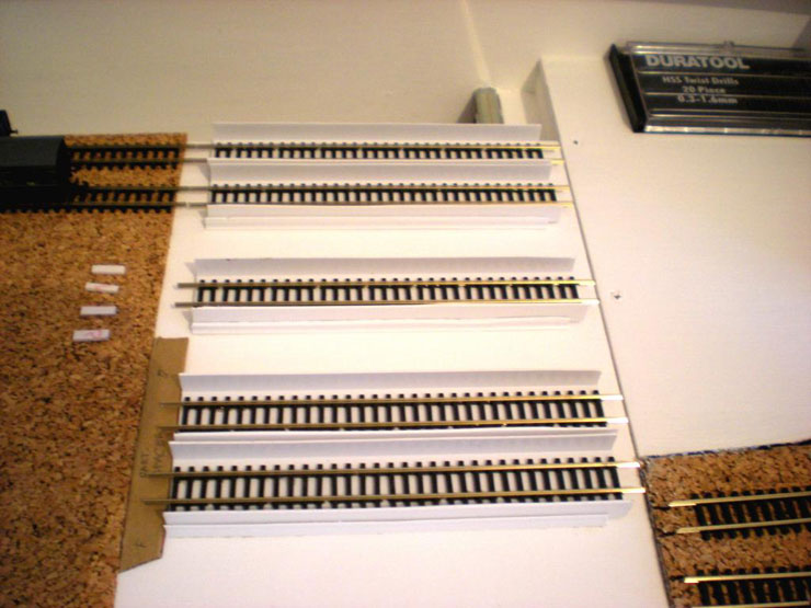
A quiet week after Christmas meant that I was able
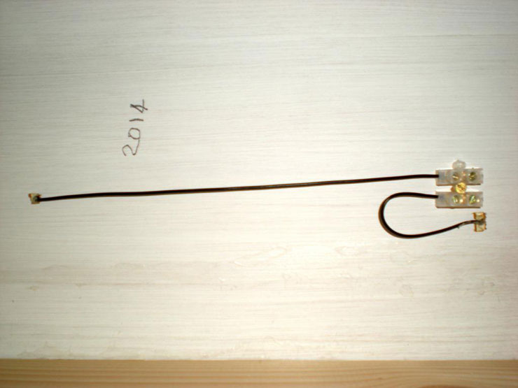
to push on with electrics and fiddle yard work. My unpatented fiddle
yard-to-traverser connecting rail with power transmission. Otherwise
known as a scruffy piece of brass and card with some dodgy soldering
to secure it. It works pretty well, but I'm betting that a much
tidier version can be made, just not by me:
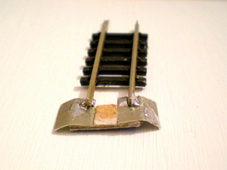
Here it is in place. The curved sides allows each
of the traverser storage lines to ride over it as the traverser is
pulled out:
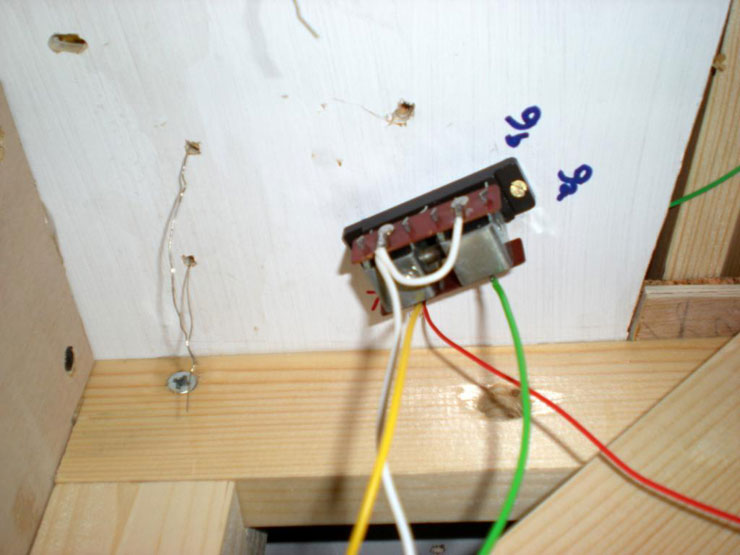
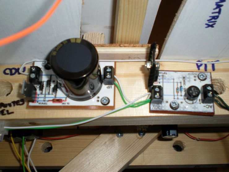
And meanwhile, underneath the main board, the PIT
(a power board and plugged-in power supply) and CDU have been
installed:
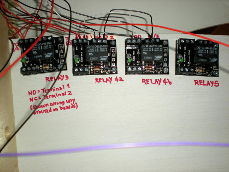
Two more relays attached (Relay 4b is solely to
allow the fiddle yard to be taken over by Controller 3 while 1 &2
still power the main line). Writing upside down with a felt pen is
fairly tricky:
The route setting board:
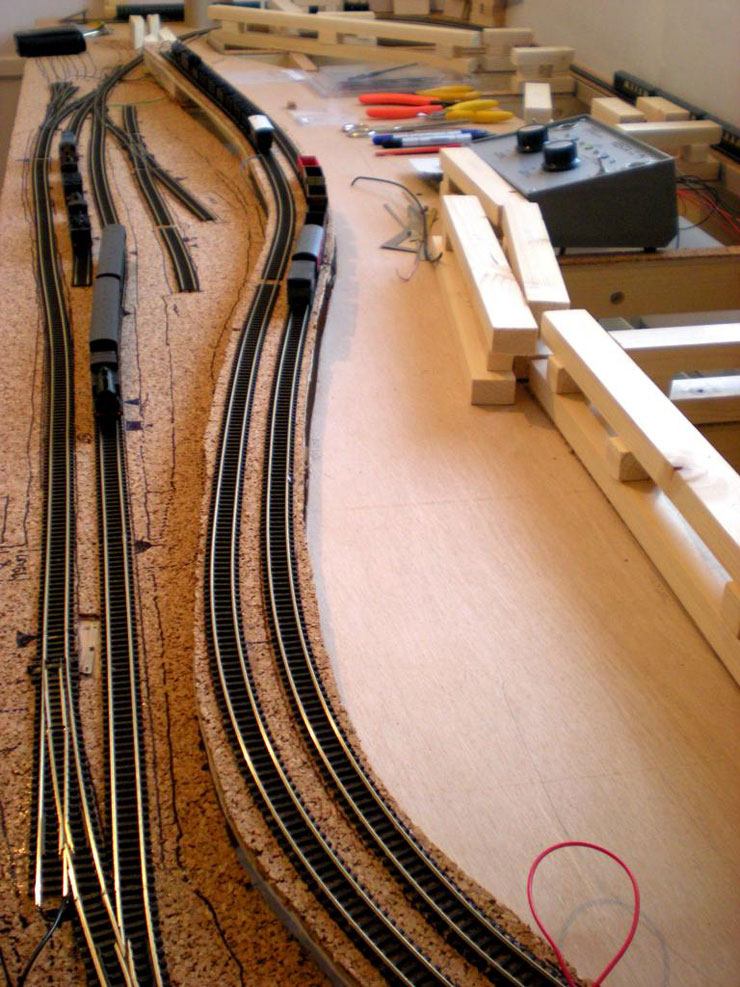
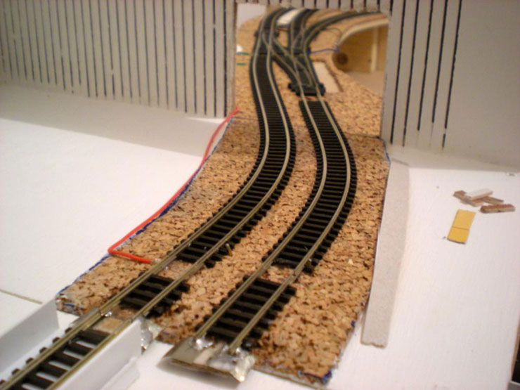
And finally for now, the main line reaches the
fiddle yard!
|