|
2 May 2016
Work on the layout has been trundling along at a
fairly good pace, but I haven't had a chance to post individual
reports, so this one is a bit of a bumper photo-fest. In fact it
covers all the work carried out during February, March, and half of
April! I really shouldn't leave it so long between updates...
As usual there are far too many jobs that
need doing, sometimes so many that I don't even know where to start
with them. In the end I usually end up working on two or three of
them at the same time, with the result that progress is slow on all
fronts.
Still, progress recently has been good -
especially in overall visual terms. Something I've wanted to get
installed for a while has been the front fascia. But because of the
way I wanted this to link into the platform at the very front of the
layout, the platforms had to go down first. The first go at this was
botched, because I glued together two layers of balsa to produce a
platform that would need steps up from the carriage for it to
be reached - provided the carriage doors could even be opened outwards
(there were no sliding doors in 1930, you know).
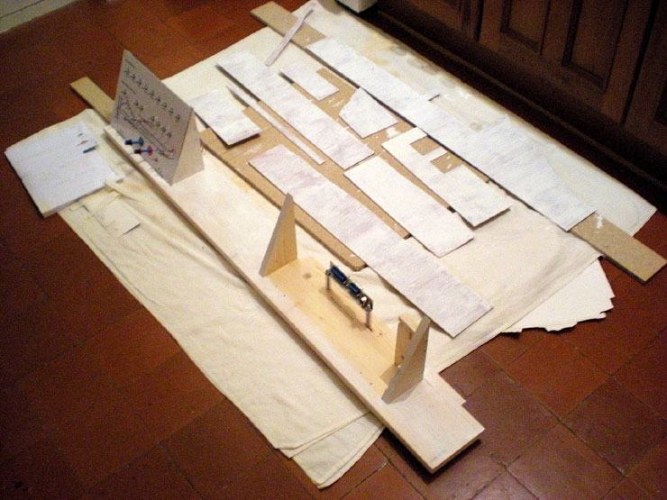
The second stab at this went back to
basics. The first thing to produce was a decent template for each
platform, and as always, card is the best resource for this.
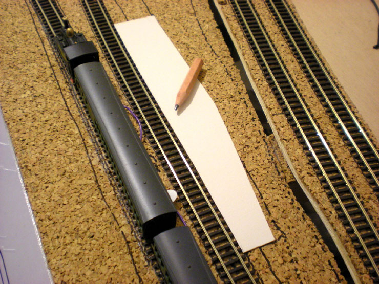
The balsa that I'd bought for the platforms was still a little thin,
so it needed two layers glued together and a layer of cereal box at
the bottom. That done, it seems to be pretty much perfect. The
platform height falls at just around the height of the running board
on Farish suburban carriages, which means a short step down from
the carriage - common enough at most stations even today.
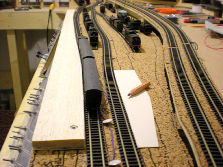
Platform 2 now in place. Because the balsa was a little warped,
screwing it down
seemed the best option. The screws can be covered
with card and the whole
platform will be washed over with shades of
grey. Eventually the sealed holes will
look like patches of tarmac
that have been reworked at some point. At least, that's
the plan.
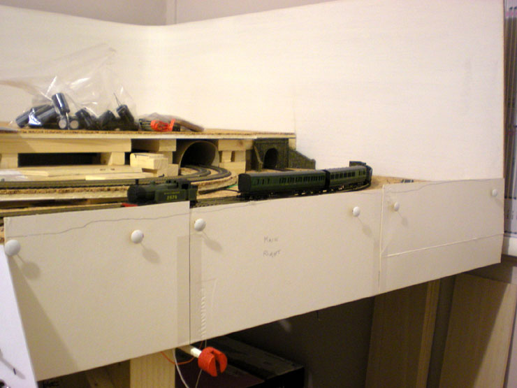
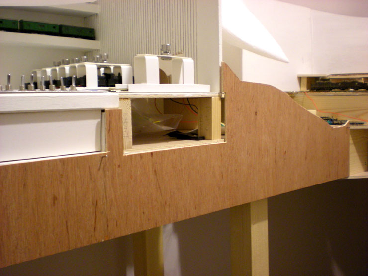
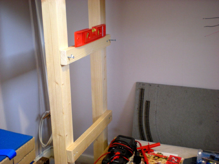
Now for a bit more work on the upper level's MPD board (the
left-hand of the two
upper level boards).
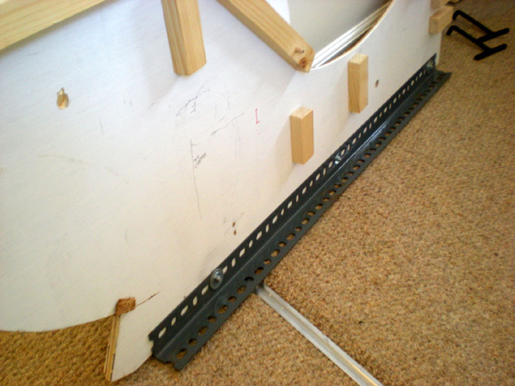
The boards were still far too flexible. They needed supports that
would fit underneath and not catch trains using the back straight
underneath. Metal shelf supports, kindly supplied to me, were
measured and cut down using my trusty junior hacksaw. Then they
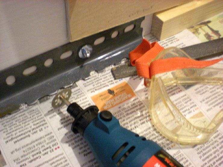
were bolted in place and the extended bolt thread was 'dremmelled'
off at the nut.
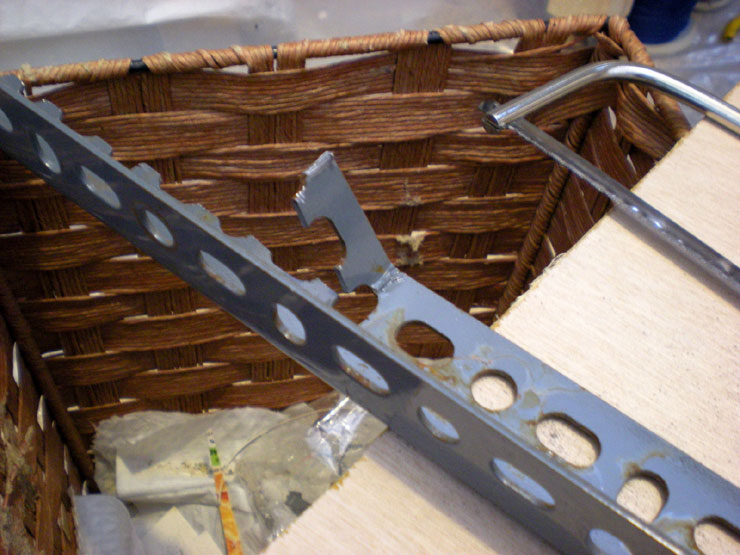
But then I discovered that coaches coming onto the back straight
underneath were
catching the first part of the support on the Bournemouth West board, so it had to
be reduced
in depth. More trusty junior hacksaw work. Quite a bit of it, in
fact.
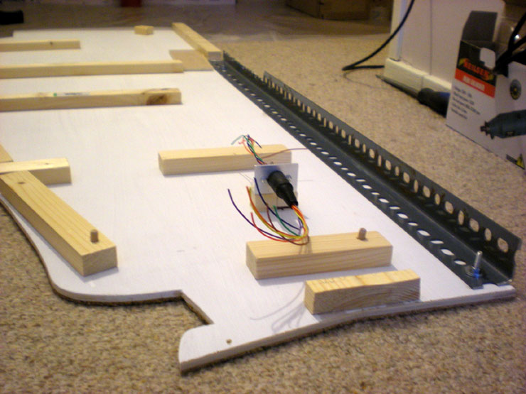
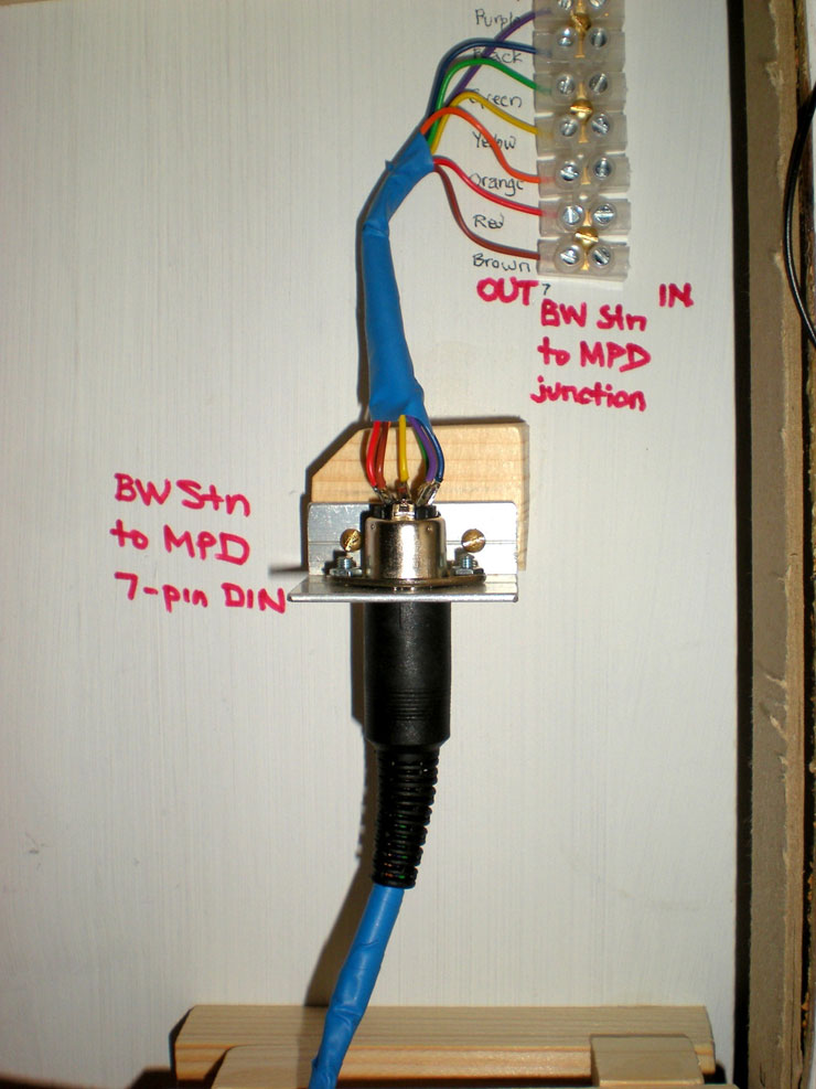
That done and tested to satisfaction, I could turn to adding the
wiring connection
from the lower level, which would be supplied via
a 7-pin DIN. You can also see the
hacksaw work done on the shelf
support, at the far end.
Bolt holes covered on the upper surface.
Detachable wiring connections between the two upper level boards.
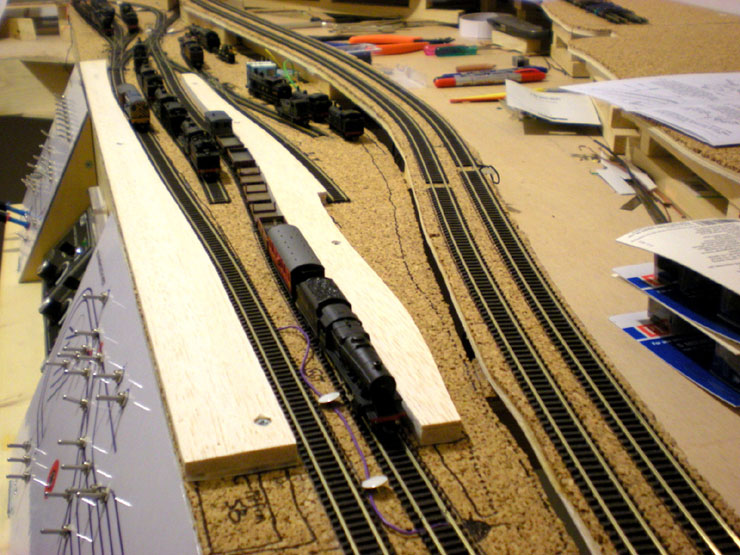
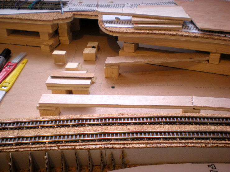
And now for something completely different. With the front platforms
in place, it's
time to create a
template (out of cereal box) for the front fascia. The pencil line
marks the upper edge of the fascia, which is designed to provide a
scenery level
between the front of the layout at the track.
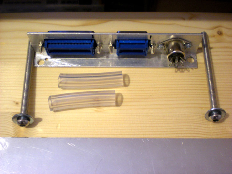
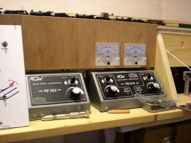
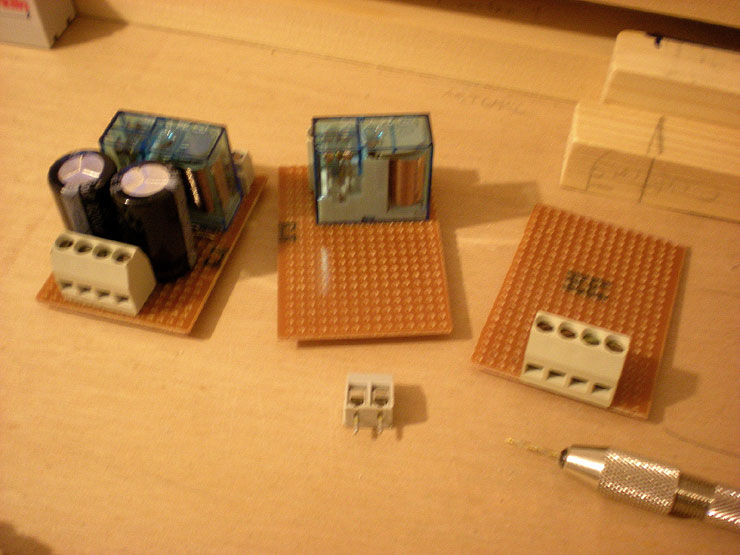
Assembling the first parts for the Bournemouth West (BW) control
panel.
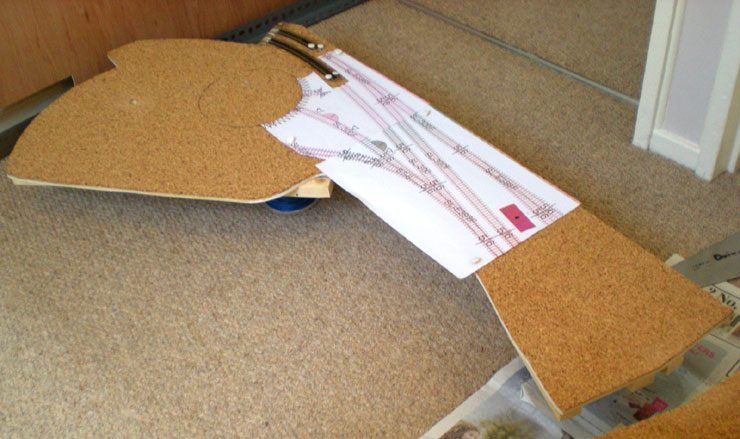
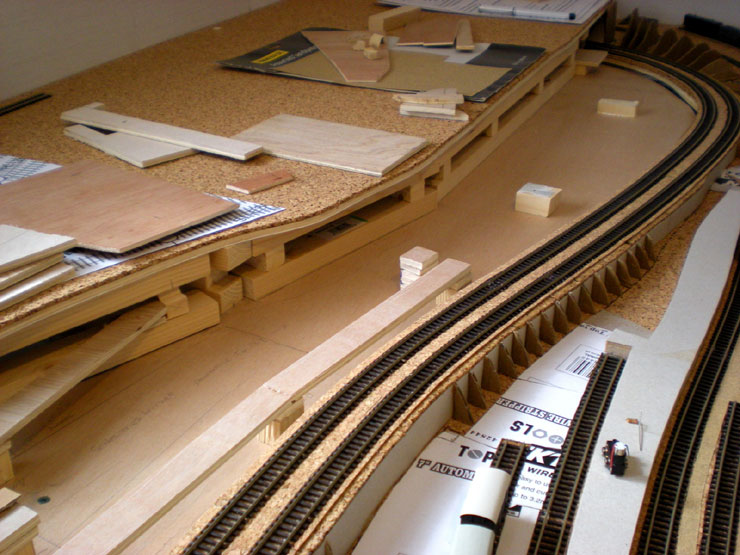
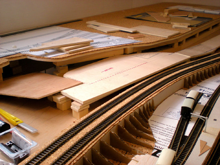
The fascia template is being turned into plywood reality. One test
fitting in between
the two control panels coming up...
...and another over on the fiddle yard.
Back to the heavy duty upper level work - this all has to be done
before any
serious track laying takes place.
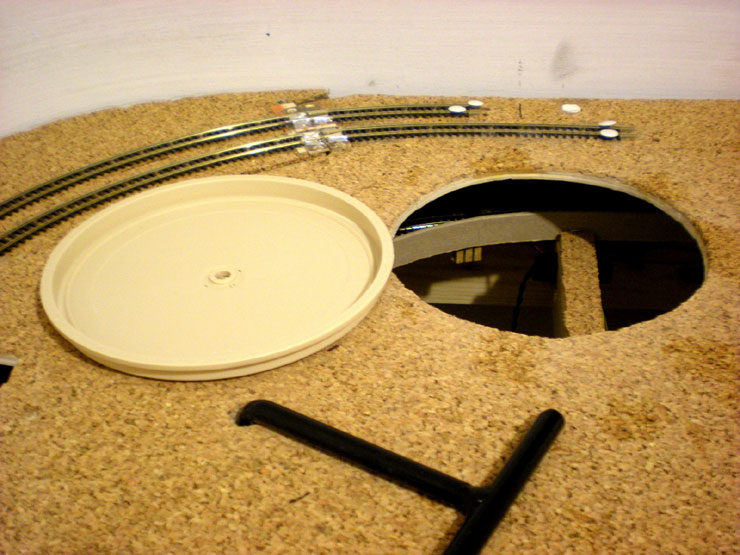
Sawing and filing out a hole for the Peco turntable
was a job and a
half!
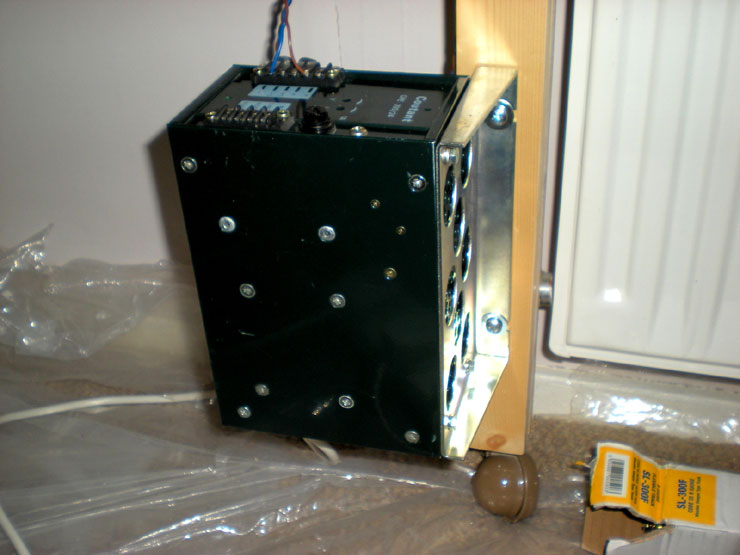
Undercoating the fascia meant that I also had the opportunity to
paint the control
unit.
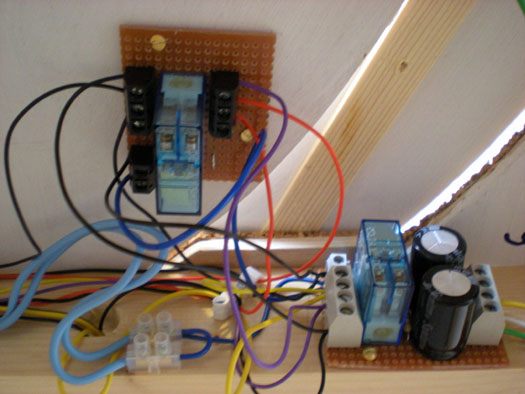
A CDU with a bit of oomph for the points, now installed on the
layout like a humping
Chihuahua.
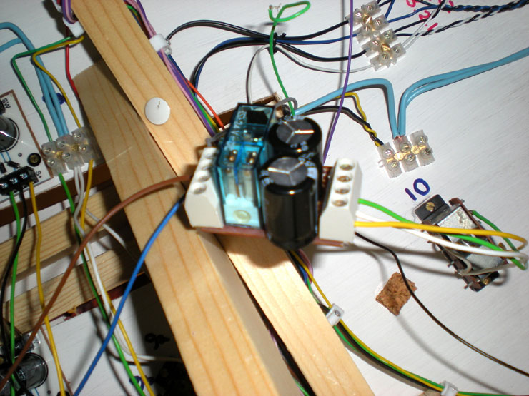
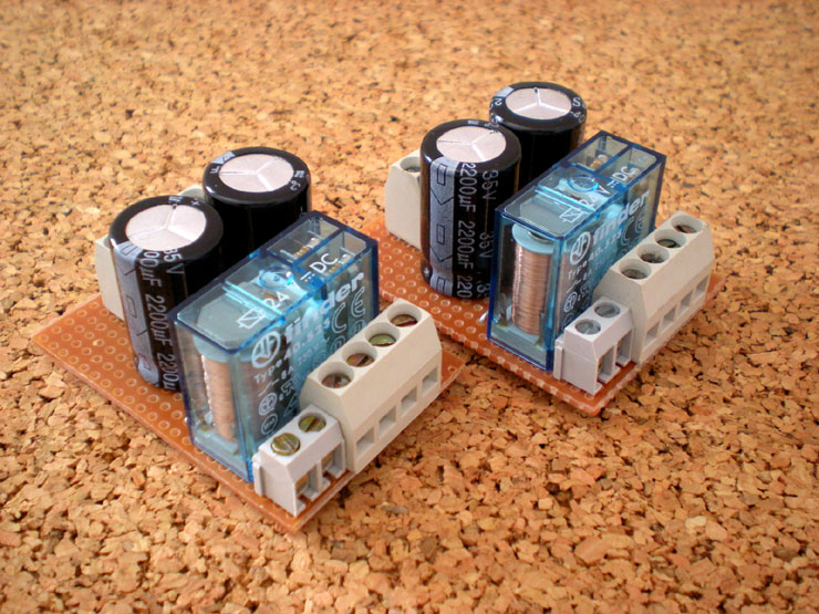
The first purpose-built relay to control the route setting points.
The original system
of diode boards and relays is being dumped in
favour of this much more
straightforward system (and this one
actually works!).
The painted control unit is back in position.
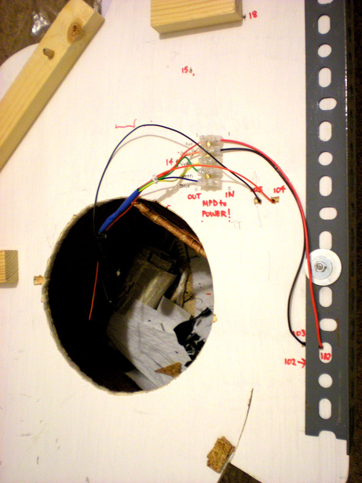
Wiring the MPD board to the lower level via a 5-pin DIN (the DIN
plug is resting
inside the turntable hole).
Overcoating the fascia, one of three coats of satin paint for extra
protection, plus
two coats of matt varnish (which unbelievably is
still in top class condition, around
fourteen years after I first
bought it!).
The next stage will be fitting the fascia, but that's something that
will only be
reported when I get around to transferring the next
batch of photos from my aging
camera.
26 May 2016
It was time for a grand weekend of works. Having a
three day bank holiday weekend meant there would be a good chance of
getting everything done. Announcements were duly made in advance:
'The line will be closed all weekend for engineering works. As this
is 1930, no replacement bus service will operate, but passengers are
free to flag down a fly or hire a local cart to transport them to
the next working station. Third class passengers may walk using
local paths and trackways'.
All of the planned work involved the back of the
layout, so some time was spent in removing the control unit and the
fiddle yard and the upper levels, and even the really-hard-to-detach
incline curve. With all that missing, along with the backscene, this
is the view.
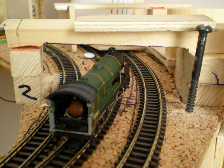
The top of the incline, on both sides, needed lowering to remove a
peak at the
crossover point. That meant lots of shaving and sanding on the
underside of the
MPD board (with turntable hole visible here)...
...and sanding to the final support for the incline curve. I also
took the opportunity
to create some clearance space for the chunky, nose-in-the-air King
Arthur. That
involved lots of filing on the underside of the support bar. Lots
and lots of filing.
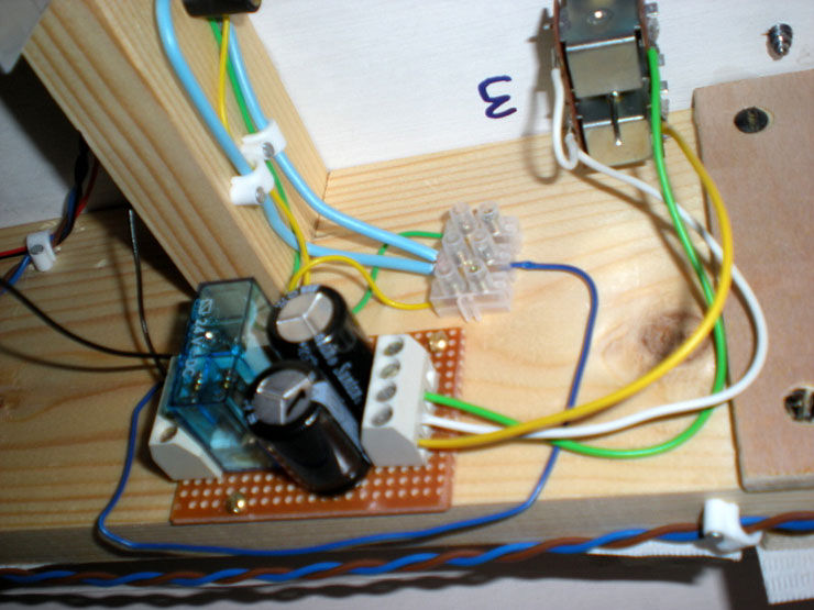
Then the points motor for Point 3 (located just behind the King
Arthur's cab in the
photo) was installed and tested. That's the last of the lower level
points to be
installed. At last.
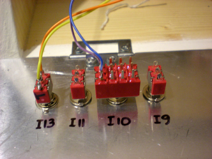
Another job was chipping out a bit of extra space on the control
unit for switches...
...and also attaching three dust cover sheets to the back of the
layout, just below
the removable backscene parts.
The smoothed incline top looks much better now. Locos and stock seem
to glide
over it. Not one derailing has occurred. Job done.
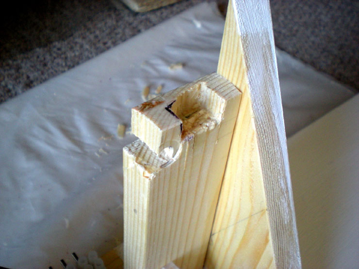
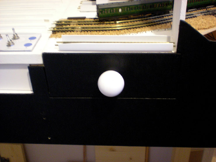
The next job was to create dust sheet support posts from scrap wood,
with
notches. The idea is that these will be the stumps and the notches
will take the
bails.
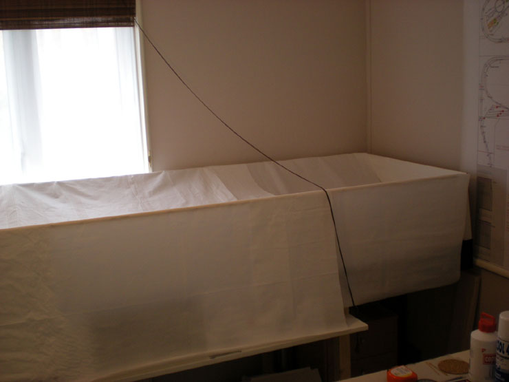
As you can see in the next shot, the front fascia has been fully
painted, fitted,
tidied up, and varnished. All it needs to complete it is a black
curtain (in four parts,
but that's for another day).
The dust cover support stumps have also been fitted, and the 'bails'
are in place.
There's a little tightness where they meet the stumps, so there's no
chance of
them wobbling or falling off. They're pretty secure when in place
and still easy to
remove when dismantling the structure.
The same job was done for the fiddle yard.
With the dust covers in place, all the work at the back of the
layout completed and working satisfactorily, and the fascia
finished, it feels like a milestone has been passed.
11 June 2016
Well, that milestone proved to be a bit of an
excuse for doing nothing. To be fair, work has been busy this month,
and the History Files needed a bit of attention, so the layout has
remained under its dust covers.
Must find a way to stop the covers sinking down onto the layout. I
have something
in mind that may partially solve that problem.
12 June 2016
There was one other thing that I forgot to mention
from the layout work before the recent hiatus. An accidental drawer
space under the fiddle yard that is now complete with draw. It's
nice when a plan comes together, even if it wasn't really a plan to
start with.
I've recently also had a booster shot of enthusiasm,
so there's more going on to report next time.
4 April 2017
It's been a long time coming, but work on the
layout this year has really moved things along.
Two major electrics sessions have completed the
main work on the route setting. Now there are just one or two
potential creases to iron out, plus some work on adding
relays around the points to provide the proper power feeds when
points are changed.
First off, a tunnel mouth bought via eBay for the
single track lines out of Evercreech Junction towards the back
straight.
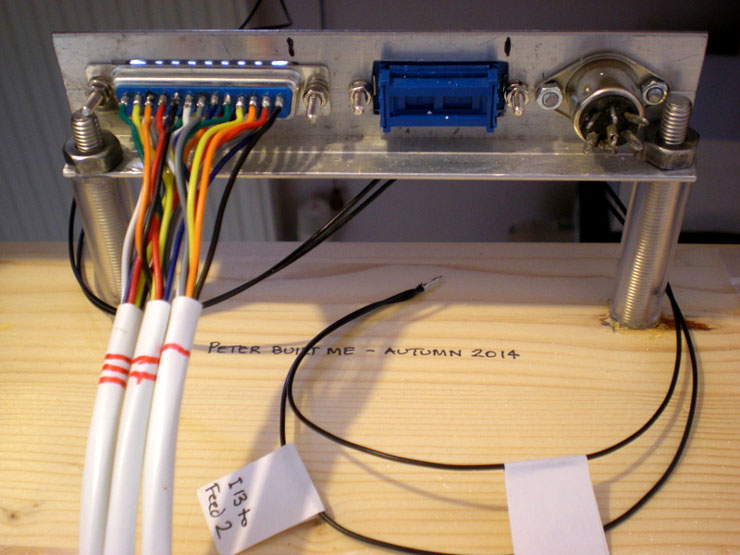
And now for the scary part - elektrickery. The Bournemouth West
(BW) mimic panel
finally gets some wire added to its empty innards. All
of these wires fit a D-plug on
the other side of the control panel
pull-aparts.
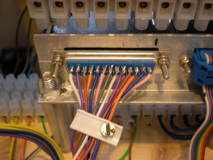
The Evercreech mimic panel also needed a bit of work with the
D-plugs after
several of the wires came loose during work inside the
panel. My soldering these
days is a good deal better than it was two
years ago, and I was able to re-solder
all of these without taking
the entire section out.
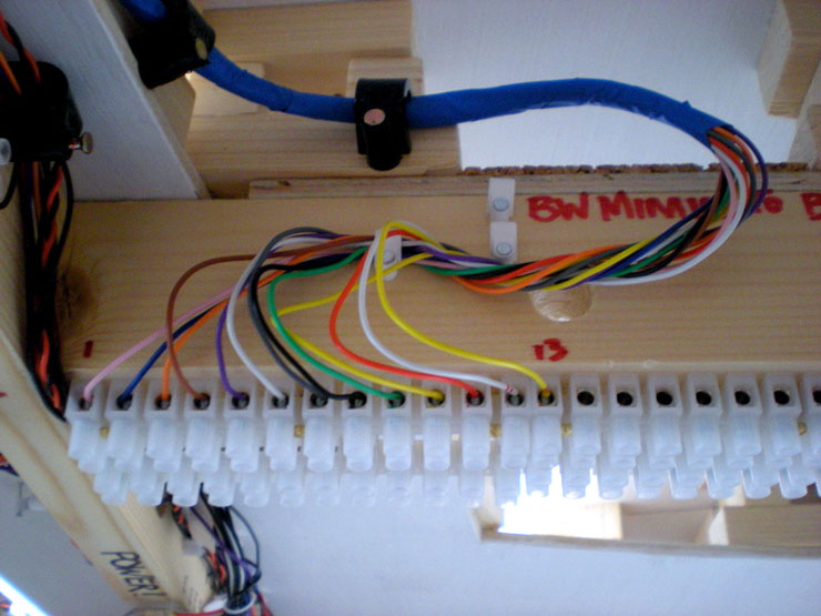
The BW D-plug leads here, to a batch of choc
blocs under the upper level. I love
chocs. No soldering required.
All of these connections will carry power to the upper
level.
Also added to the BW mimic was the wiring for two isolating
sections, both on the
incline between upper level and lower level.
The one coming down the incline was
always planned, so that trains
could be stopped if the route onto the back straight
wasn't clear.
The one going up is a newbie. If a particular train proves too heavy for a loco, it can
stop, the driver can walk to the nearest signal
box or level crossing keeper (it's
1930 - not only are phones not mobile, a great many people don't
even have one
yet!) and put in a request for a banking loco to pull up behind the train and give it a
push. It works, too.
Underneath the layout, the route-setting points are getting their
relays added.
And added to these are points feed relays which control power
distribution on
either side of the points. You can't rely on the points blades to do
that. Point 6,
above these relays, recently stopped doing just that because the
blades weren't
making full contact, and that happened not much more than two years
after being
laid.
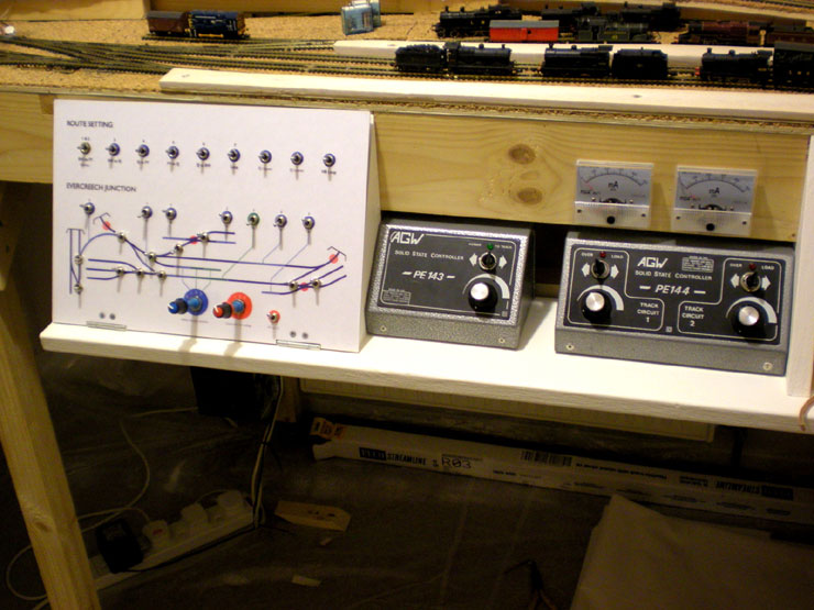
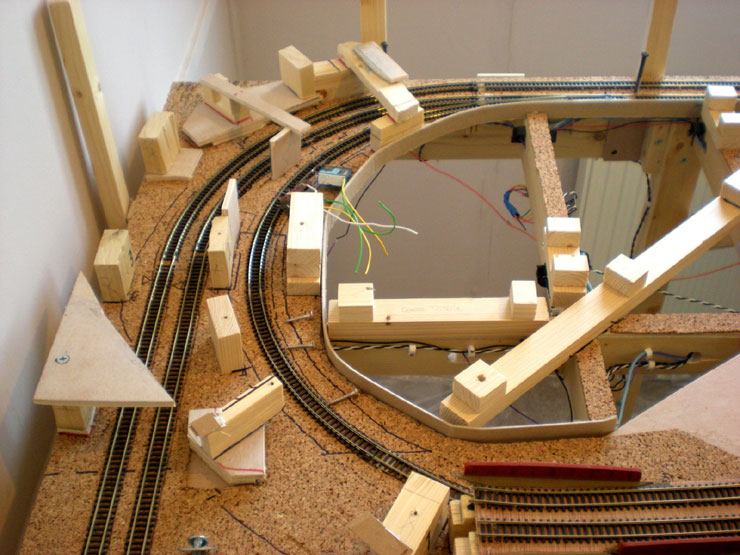
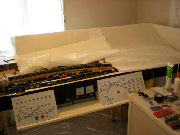
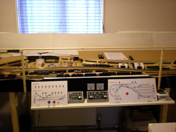
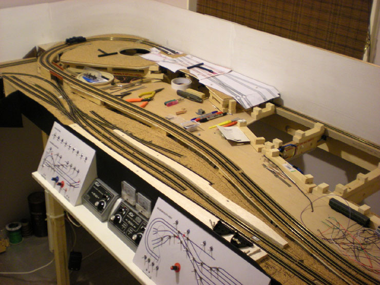
Fancy an overview of the layout? There's Evercreech Junction at the
front, the
detachable control panel below that, and the incline up to the upper
level behind it.
Entrance to the fiddle yard is on the far upper left-hand side of
the photo.
Finally for this time, two more route-setting relays were required.
They're not
actually for the route setting. These are to serve one of the more
complicated
points/wiring set-ups - a point connected to a double slip, which
means three
motors in all, and quite a bit of feed wiring.
Done. With these installed, Points 30 and 31a/b all work perfectly,
I have power
into the colliery sidings for the first time, and I can even switch
control of the
sidings to Controller 3 while controllers 1 and 2 have the main
line. It's all coming
together.
30 April 2017
There seems to be a lot going on with the layout
since the end of winter hibernation. The electrics on the lower
level are coming along nicely, route-setting is largely working as
hoped during testing, and now it's time to begin a few basics for
the scenic side of things.
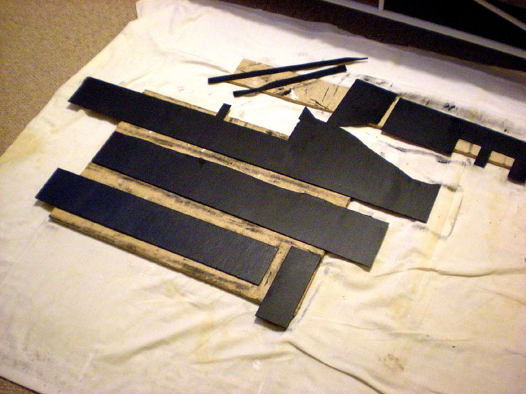
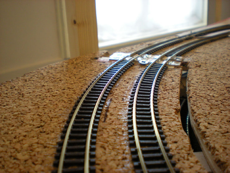
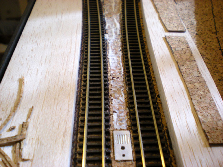
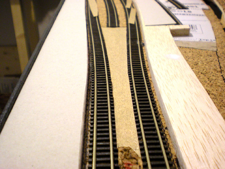
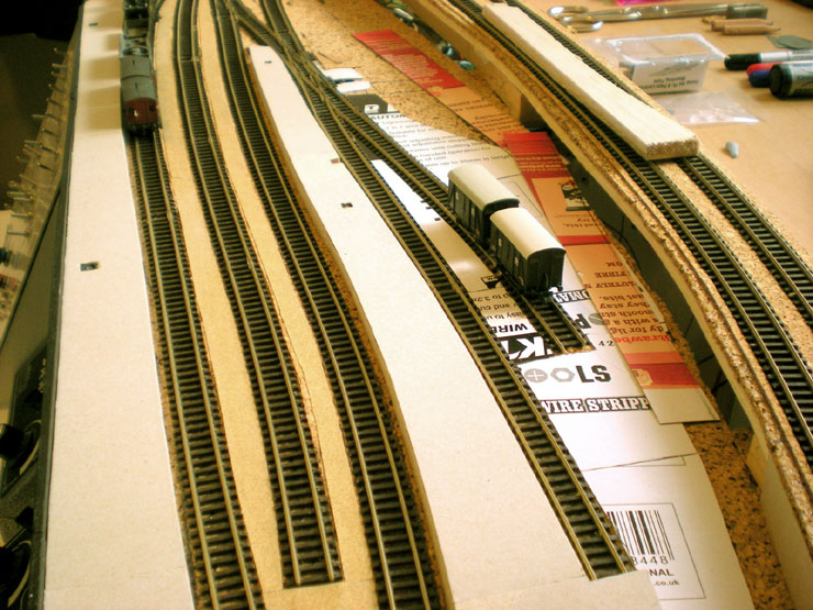
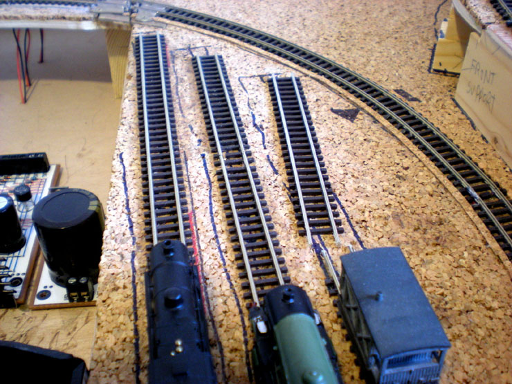
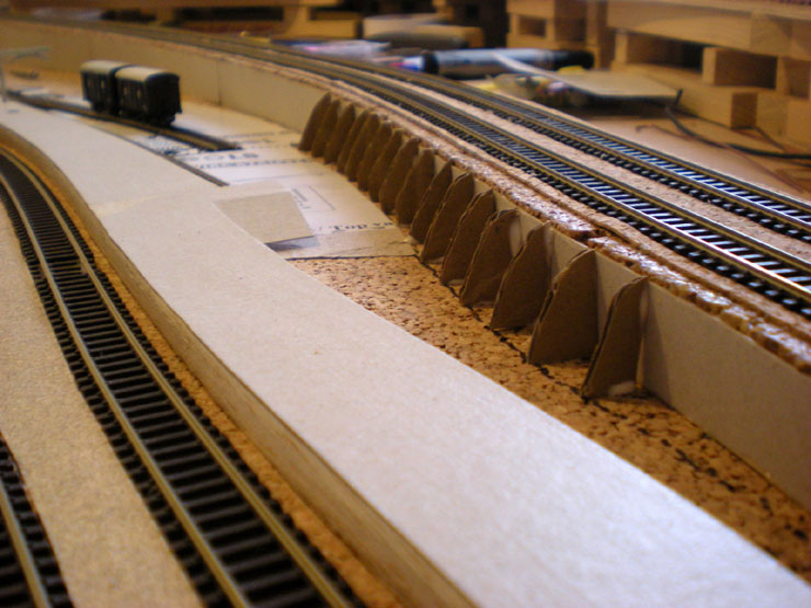
To start with, I've long wanted to do something
about filling up the gap between twin tracks so that when they're
ballasted the ballast will appear fairly level. Pre-war railways
tended not to have deep ballast troughs. In fact they seem to have
ballasted up to the top of the sleepers and levelled that across the
entire trackbed.
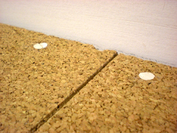
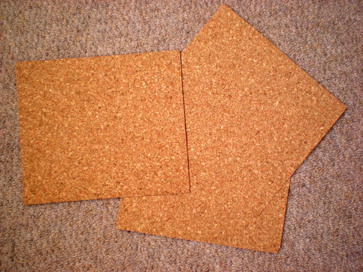
To help with this, 1mm cork sheets were ordered.
These will be cut up and laid between the tracks. The bonus is that
cork is flexible, so cutting them out can be relatively rough and
imprecise. You just jam then in and they take it.
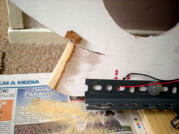
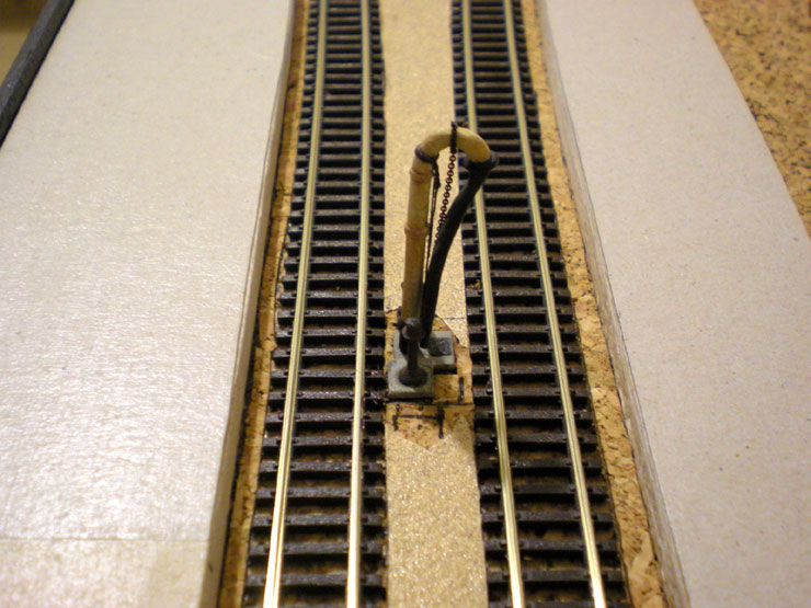
The first few strips were laid over a crank set-up
for a points motor that couldn't be
laid directly under the point. Lots of testing made sure that the
crank still worked
after laying.
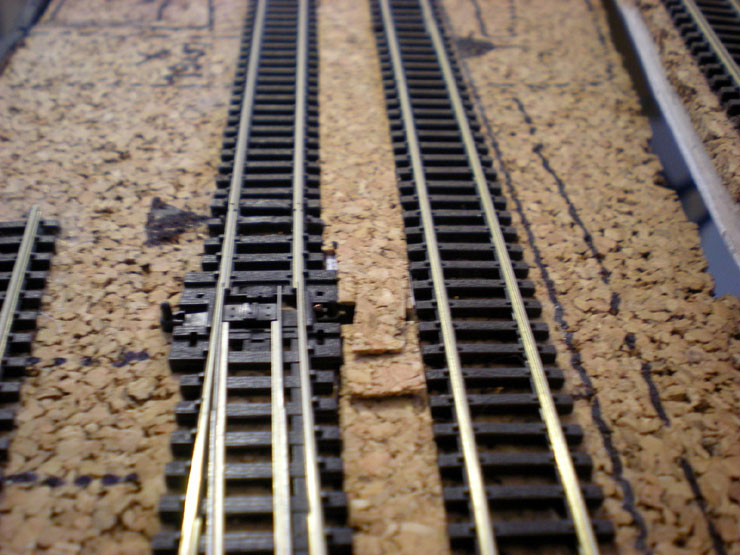
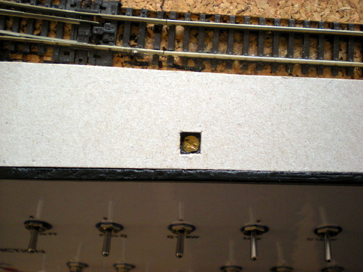
More cork went down the entire centre strip at
Evercreech, allowing the water
crane's base to be inset into it.
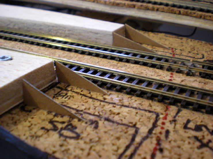
More work on Evercreech - platform ramps are
coming!
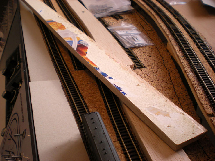
A rethink on the platforms themselves means that
the balsa will be protected by a
layer of grey card (cereal packs are a great source). The balsa is
just too fragile to
be left out in the open, although it's still great for making curved
platforms.
Because the platforms would be gaining a layer of
card on top, a layer of card had
to be removed from the bottom.
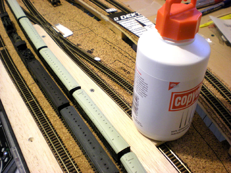
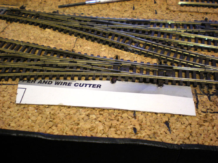
Also, now that I've got more information on the
goods yard at Evercreech, I
decided to realign the goods shed line a little, and extend it a
little too. Gluing is
taking place, with something heavy to hold the track in place for
twenty-four hours.
Here's the base layer for the road and level
crossing. A top layer will hide all the
print.
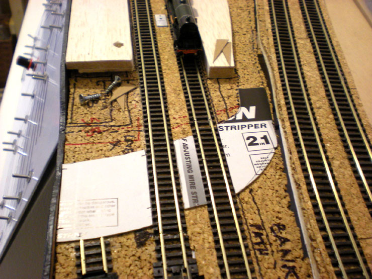
More card to hide another points crank. This one
was also fully tested many times.
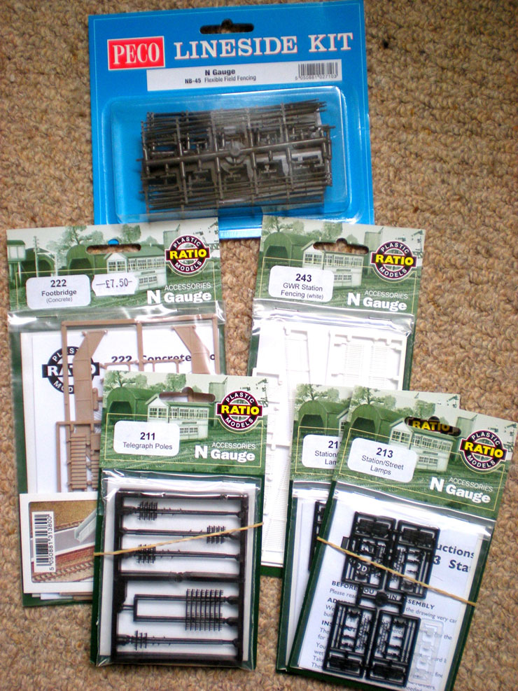
Finally for this update, a host of goodies just
arrived. They're all for Evercreech. The
lineside fencing will be used in the cattle dock (the fancy Ratio
dock is far too big
and showy for Evercreech).
The footbridge will have to be hacked to narrow
the track span. The GWR white picket fencing will be used on both
platforms near the level crossing.
The station lamps are a perfect match for
Evercreech, and the telegraph poles may
need some minor hacks to make them suitable. I also have 'stone'
paper for the
platform facings and for scratch-building the station master's house
and other
buildings. Not really looking forward to that part...
11 June 2017
With the Gloucester show coming up next weekend,
it's time for an update on progress with the layout.
The lower level electrics aren't far off
completion, with the only bits outstanding being the old the relays
at the back, the wiring for the Evercreech Junction goods siding,
and the relays around Points 1 which also supply power to the fiddle
yard.
That leaves me free to start on the scenic work on
the right-hand side of the layout, and on Evercreech Junction (EJ)
Station itself. The balsa platforms are being supplied with a layer
of card - Coco Pops seem to offer a good shade of grey for this, and
their boxes are quite big (more card, less joins).
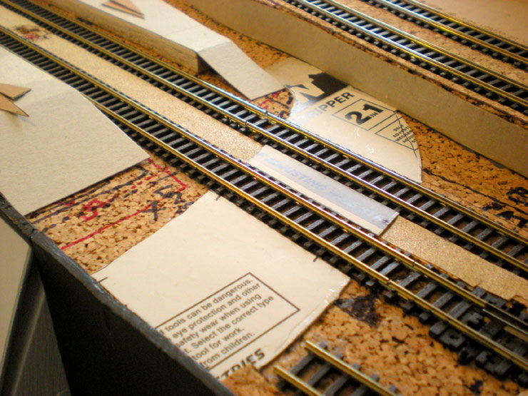
I've also added a layer of fine grade sandpaper
between the tracks. When the ballast is down around the track
itself, there will be some texture in between which should resemble
finer grade ballast and general grit and gravel.
Where possible I'm securing platforms by screwing up from
underneath, but near
the EJ control panel this isn't possible (to much electrical gubbins
underneath). So
these bits need top level screws which will be covered over later.
With the platform surfaces finished, they were given a coat of matt
varnish to seal in
the card. The sandpaper-laying was finished, and the open nearside
embankment
was sealed up.
The beginnings of a level crossing were added to the right-hand end
of EJ station.
The completed water hose kit was put in place (see the workbench
thread for
details of what needed to be done to complete this white metal kit)
- it's the first
bit of completed detailing for EJ station.
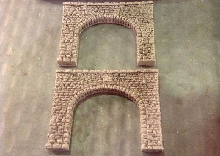
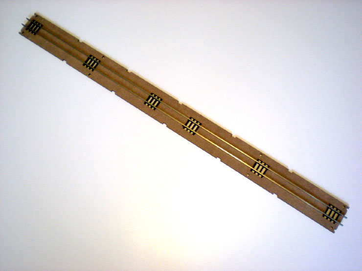
Something I've wanted to try out for a while is the rolling stock
cartridge from Mill
Lane Sidings. Made of laser-cut MDF, it's assembled as a kit, with
the track going in
first of all. The remaining sleepers are supposed to slot in place,
but mine needed a
good dose of superglue to hold them there.
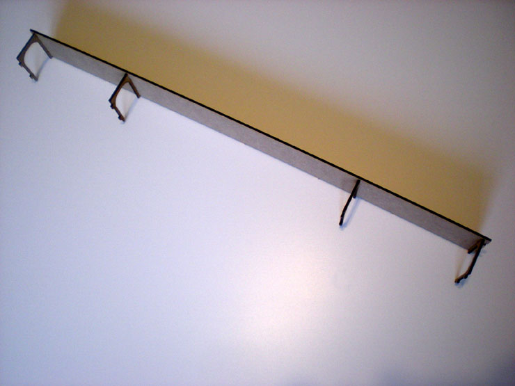
The next stage is to assemble the side panels and arches.
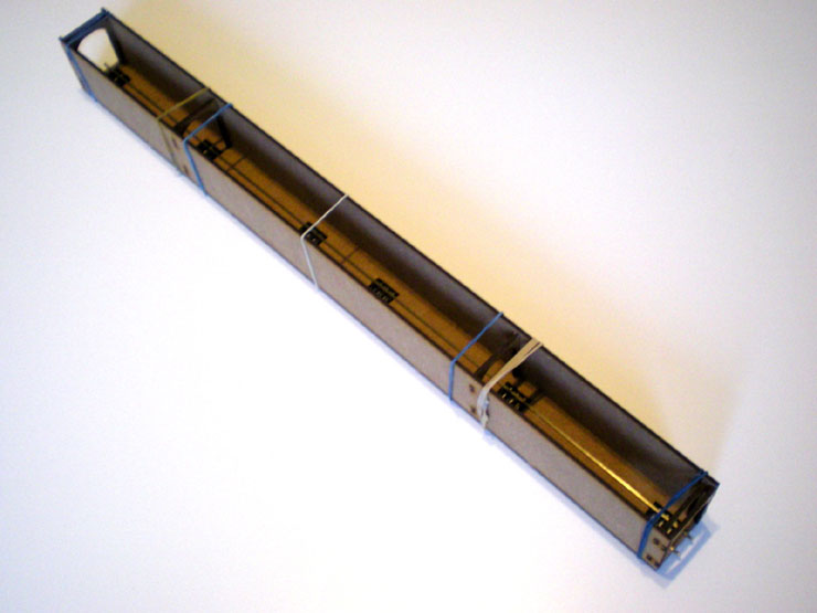
Then it all gets joined together and held in place with elastic
bands until the wood
glue dries. The completed kit is pretty robust and easy to handle,
and apart from
the rail problem assembly was very easy.
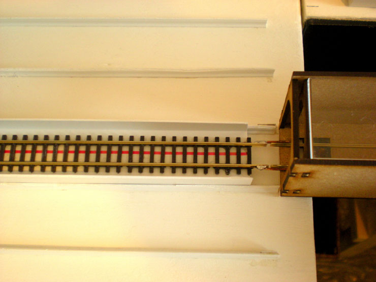
Then I needed some way of joining the cartridge to the fiddle yard
so that complete
trains can be loaded and unloaded - or at least half trains can, as
the cartridge is a
touch over three coaches in length. I can't double up on cartridges
because there
isn't enough space between the fiddle yard and the layout.
A custom plastic fiddle yard tray was made up, with a couple of bits
of brass rod
soldered on the outside of the leading end of the track so that the
cartridge will sit
inside it. This has the effect of aligning the tracks, although the
cartridge did need a
piece of 3mm scrap plywood glued underneath it to raise it to the
same height as
the fiddle yard track.
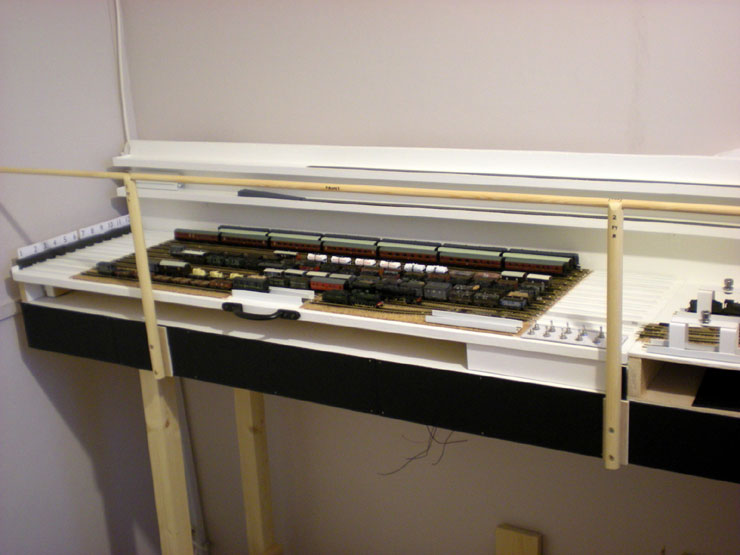
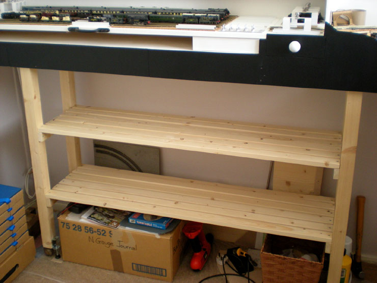
With cartridge testing a proven success - I'll certainly need to get
more of those,
but they're not exactly cheap - I need somewhere to store them.
Extra shelving
under the fiddle yard is the ideal place.
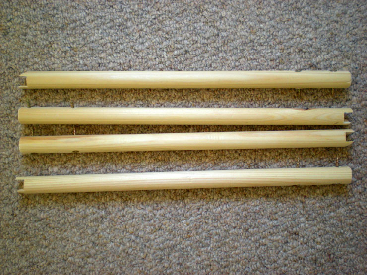
With some strips of pine ordered for a DIY job in the house, I
increased the order
to give me enough for this shelving too. Viola! Two shelves of
additional storage
space.
And now for the moment you've all been waiting for. The final piece
of track to be
laid on the lower level. It was the offcut from creating the
cartridge-to-fiddle-yard
tray.
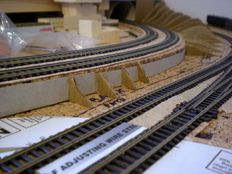
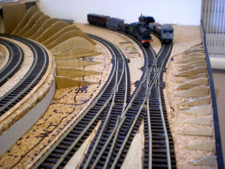
Now on with laying the basic structure for the embankments and
cuttings.
Corrugated card will do for this, cut roughly to the shape of the
eventual scenery.
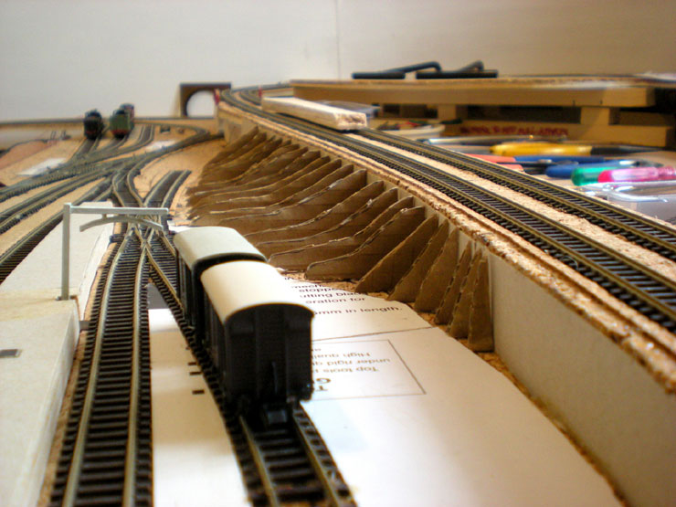
The gap on the other side of this bit of embankment is where the EJ
water tower
will go.
A steep embankment will also sit at the back of EJ's goods yard.
The exit from EJ station and the colliery line also gets some more
contour shapes
added.
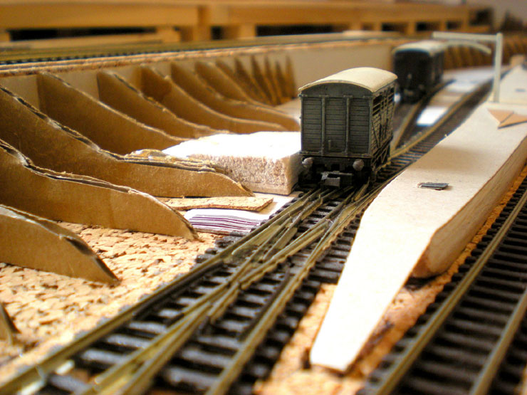
And then there's the field at the back of the EJ goods yard....
...with the EJ cattle dock now added. Unfortunately this sits right
over one of the tie
bars for the double slip in the goods siding. For that reason, the
dock needs to be
removable, just in case.
Having spent a while looking in detail at the lineside buildings
around Bournemouth
West Station (at the back of the layout, on the upper level), I've
managed to work
out a much better idea of how to fill up the empty central well. The
foundations for
the road and a terrace of railwaymen's cottages have been added...
...and the road extends further on towards an eventual tunnel
alongside the
tracks. This is Poole Road, but brought nearer to Bournemouth West
(BW) than it
was in reality and with all the grand houses removed.
The road surface goes on loose for mow. The red dotted line marks
the front of the
terrace of cottages, with the road in front of it and the sloping
entrance to Surrey
Road and the tunnel under the railway to the left. There's still a
bit of work needed
to add some 'curve' to the slope.
With the way the scenery work is moving on, there's bound to be
another update
pretty soon.
|