|
24 October 2013
Well here it is, Variation 5 of the track plan, and
probably the best so far - certainly the most tweaked and improved.
It consists of two levels, with Bournemouth West
on the upper level. Operations-wise, it offers services from BW to
Southampton/London (aka the Fiddle Yard), services to Bath (FY) via
Evercreech Junction (lower level), and EJ services to Highbridge
(FY, again), plus all associated freight movements, and a bit of a
colliery for some extra local coal movements.
I haven't gone into any wiring or set-up details
here. This is just the track plan. The colliery could do with
improving somehow, and the Branksome sections are representations
only - they are absolutely nothing like the real version, sadly. BW
is pretty accurate, though, if somewhat truncated, and the longest
platform will take a Pacific loco and six carriages quite easily.
It's going to cost a small fortune in points to
build all of this, but I can manage it in stages, starting with
the continuous loop.
Lower level:
Upper level:
25 October 2013
It kind of has the right feel to it, trying to get
the best Evercreech and Bournemouth West that I could fit into the
space.
I've taken a look at inserting another set of
points at the junction at EJ, but the only ones that will fit are
Setrack ST-5s or ST-6s. The rest of the track is Code 55. I can't
see how else a possible loco siding can be added there, but on the
plus side, the middle road siding between the two main lines was
always used for stationing pilot locos as well as the Highbridge
train when not in use.
There's also 145mm of loco siding to the north of
the station area, left of the small goods sidings. It should
accommodate a 130mm-long Fowler 0-6-0 4F, and most tank locos.
Points motor clearance at the back of the layout is a very good
point (no pun intended). The board height for the upper level is
50mm above the lower level, which is not much when you start adding
motors. I can see seven points on the upper level that lay over
track on the lower level, and will need to be careful to make sure
that nothing clashes.
Three of those points are in Branksome Goods (if
you include two motors for a 3-way set of points). They could be
placed on the layout and masked with goods yard debris. Another
could be masked in the same way, but that still leaves three main
line points motors that could get in the way of lower level trains.
In this revision, I've inserted a single loco
siding on the western side of EJ, but to be honest, whether straight
or curved, it looks a little out of place there. The space between
the EJ curve and the London main line coming out of the fiddle yard
is going to be landscaped to provide separation between them, so
that they are clearly different lines heading in different
directions, although I'm not sure yet if the landscape will go up or
down.
Improving the gradient down from BW to baseboard
level would be a good idea as it's still rather steep.
Rather than move the right-hand set of points at
the back that lead into EJ (the entire back section will be
'underground', from the red wall line at the far left of the layout
underneath Branksome Goods, to the far right, where it emerges from
underneath BW), I realised that I could start the incline just after
those points. That now gives an inner incline (out of BW) of 1-in-53
and an outer incline (towards BW) of 1-in-56.
The height of the track as it starts to pass
underneath BW is about 0.5mm, which still leaves 4.5mm of clearance
at the tunnel mouth. That should work perfectly well, in theory (I
love a good theory ).
29 October 2013
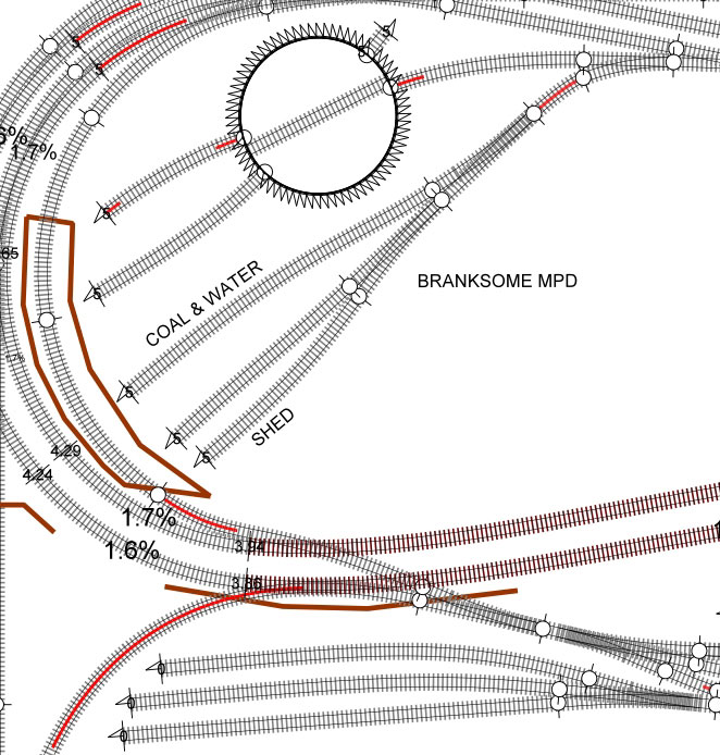
I'm not sure that I'm entirely happy with the MPD
layout. It's completely fictitious, of course, and bears no relation
to the real Branksome MPD (due to space restrictions), so I'm hoping
for a best fit with good storage space.
The version I have offers a two-lane shed (at the
top), plus a coal and watering stage with ash pit (between the top
lines and the turntable), and then a three or four-loco storage line
running parallel to the access road.
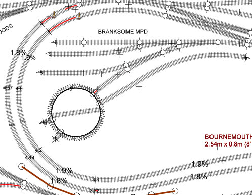
Does it need to be improved, especially given that Branksome MPD was never very large and only paid host to locos off
the S&D lines?
11 November 2013
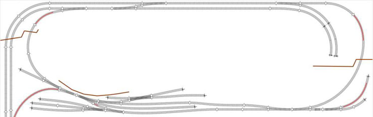
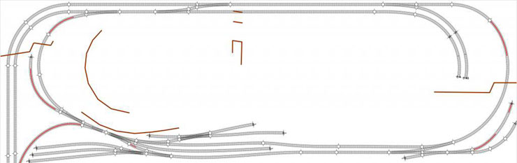
A new improved lower level track plan, showing a
better loco stabling line at Evercreech Junction (above the junction
itself, and totalling 331mm/13" in length), and a much better merge
into single track at the right-hand side of the station. This also
provides better access to the colliery sidings in the corner.
Hopefully.
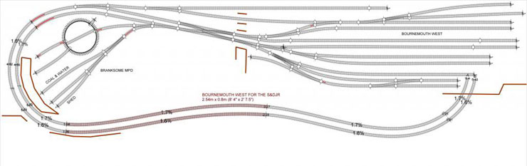
On the upper level, Branksome MPD has been
completely re-laid. This version provides a much closer 'flavour' of
the real Branksome, with two lane shed (bottom, 217mm/8.5" and
224mm-long sections), stabling/watering line (361mm/14.2"), and
turntable. Because my stabling lines are much shorter than the real
thing, I threw in an extra stabling line off the turntable (206mm),
but even the shorter line off the turntable will hold a Pacific. The
only drawback is that the shed will be facing away from the
operator.
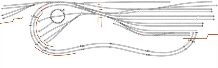
That should hold a few locos!
However, the space restraints have made the set-up
a little compromised. Access into the MPD from the five lines at top
right of the diagram will mean going quite a way out before being
able to cross over. The only apparent way to change this is to
extend the upper level to the left so that the scissors crossover
can be moved in between the MPD access point and the station.
I'm still intrigued by the idea of lengthening the
incline down from BW until it goes underneath BW and loops along the
the back straight. It'll provide a longer run out of BW, more space
for the approach pointwork, and probably allow the Branksome goods
sidings to be moved out of the far corner and inside the loop. All I
need is to get enough clearance over the EJ line and junction. I
think the biggest hitch is having the EJ junction sitting directly
under the BW incline, even if the clearance space is enough. I'll
try and work up a fresh track plan to show the rearrange upper
level.
20 November 2013
So here's Variation 6, reflecting some of the
suggestions I've received, especially in improving the station
throat and the positioning of the points at BW. It meant moving the
incline curve over to the left, where it now sits over the lower
line into the fiddle yard. It still cuts across the junction at
Evercreech, below it, but I was able to shift the points to get them
out in the open.
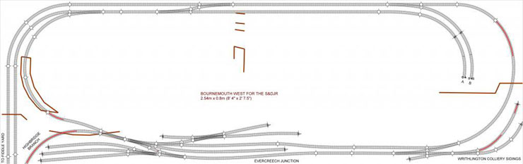
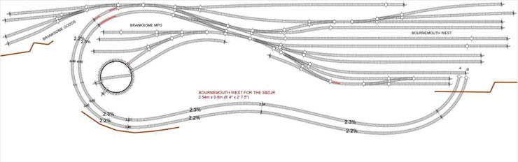
The upper section has a longer flowing incline up
to BW and longer sidings. So I've ditched Branksome Goods rather
than squeeze it in alongside the MPD. The goods and carriage lines
on either side of BW will be able to hold trains of up to around
three feet, so that should be enough.
You can see that the Highbridge branch (bottom
left, on the lower level) passes in part under the BW incline, but
this just means inserting some girders and having the incline as an
overhang.
This sort of thing happens a lot in urban railways,
but I hope it doesn't look too out of place here. Part of the line
out of EJ can appear as a brick-lined cutting (or Bath stone?)
between the BW incline and the MPD, if there's enough room to model
it. If not then I'll have to cover it entirely.
My only worry is that the incline won't clear the
EJ line properly. AnyRail gives a height of 3.86cm there and about
4.4cm when it goes over the fiddle yard exit, so perhaps EJ needs to
be lowered a tad. What's the minimum height requirement between the
baseboard (excluding track) and the underside of a bridge?
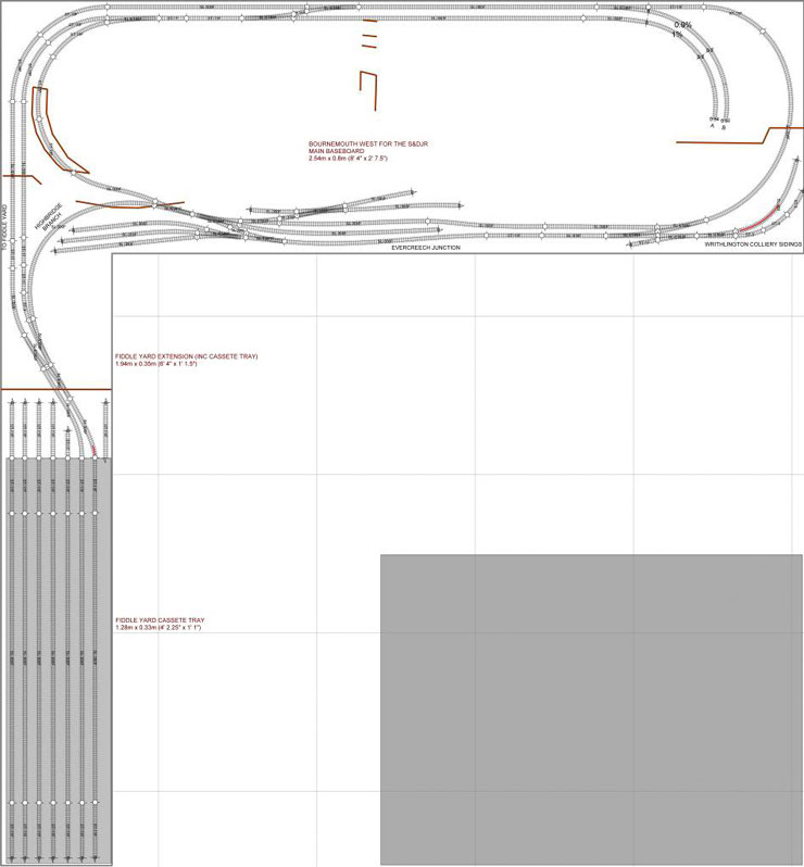
5 December 2013
I steepened the incline just a tad so that the gap
between the baseboard and the top surface of the incline is 38.9mm -
say 39mm. My tallest loco at the moment is Dapol's M7, which
measures 33mm from baseboard to the top of the chimney on Peco Code
80 track. If I use 6mm ply for the incline, that leaves clearance of
5mm (plus a tad more when I use Code 55 on the actual layout).
Better still, if I use 3mm ply for that section of
the incline (with plenty of hidden buttressing underneath) then in
theory it should still be strong enough - leaving a clearance of
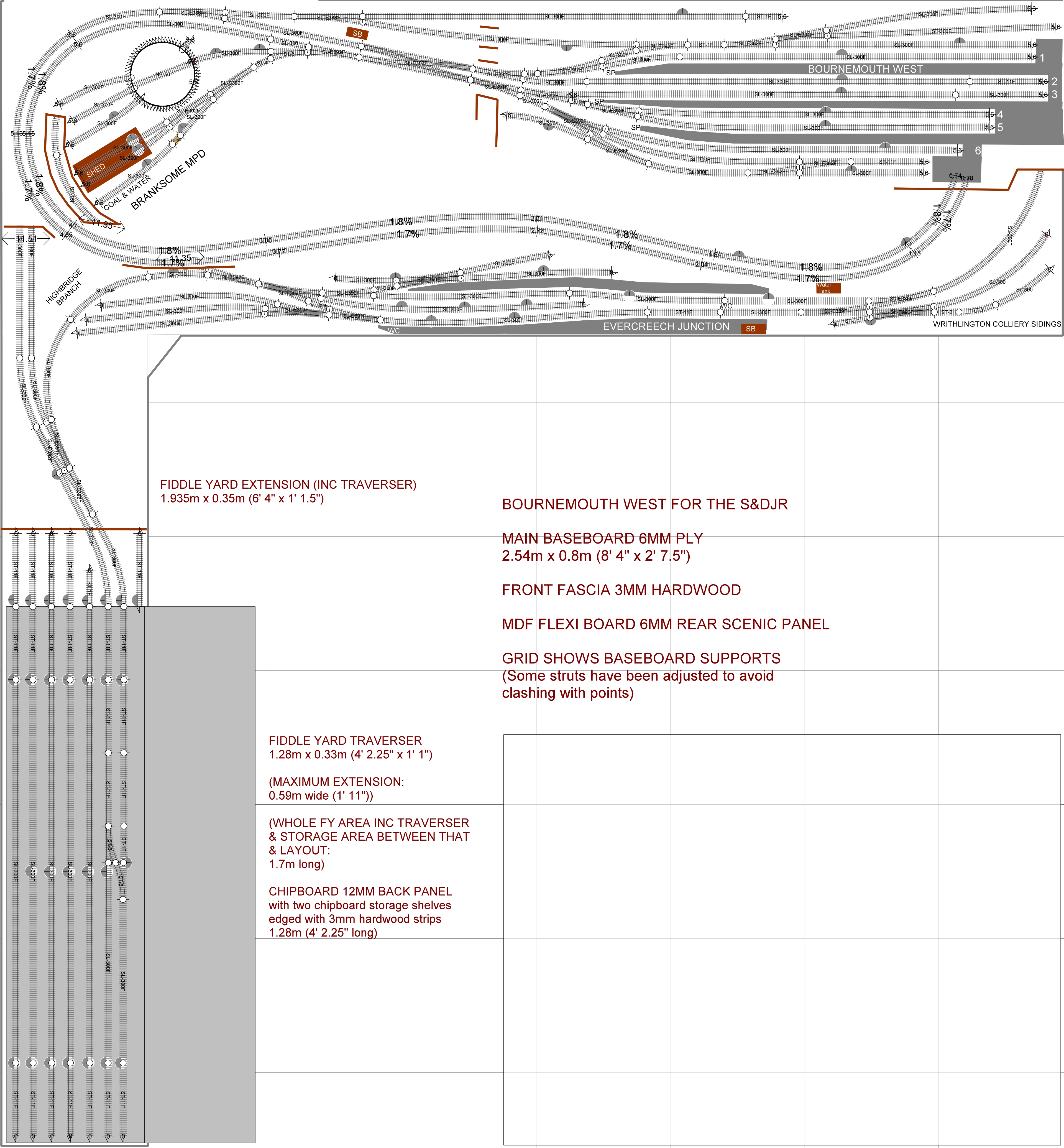
8mm. That should be enough, I think. I've put the track plan into
the context of the entire room, with the fiddle yard extension
added, to show how it should all come together. I've also added part
numbers for the track, although the Setrack curves will probably be
replaced by Code 55 flexitrack on the real thing.
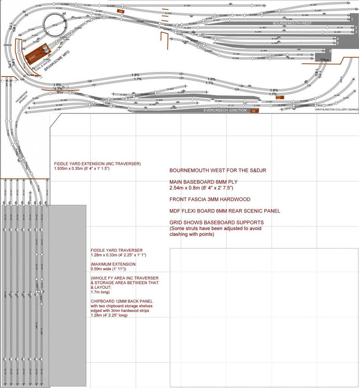
14 December 2015
It's quite a complex plan, but it offers the full
range of operations for Bournemouth West and a semi-full range for
Evercreech Junction, so when it's completed it should be enough to
keep me interested. Of course, completing it won't be a quick
process. I'm probably looking at a couple of years of work before
the track is finished on both levels and in the fiddle yard. If not
more!
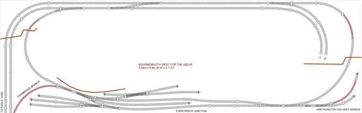
If I can get the baseboards constructed and the
Evercreech roundy loop completed by next summer then I'll be happy
enough. Here's the full track plan, with Bournemouth West on the
upper level, masking the lower level tracks at the back of the
baseboard that connect everything to the fiddle yard. (I need to run
tests on the incline, which is 1-in-59 at its steepest, just to make
sure that it isn't too steep.)
The image here is rather compressed, but the full
sized version is available when you click on this image.
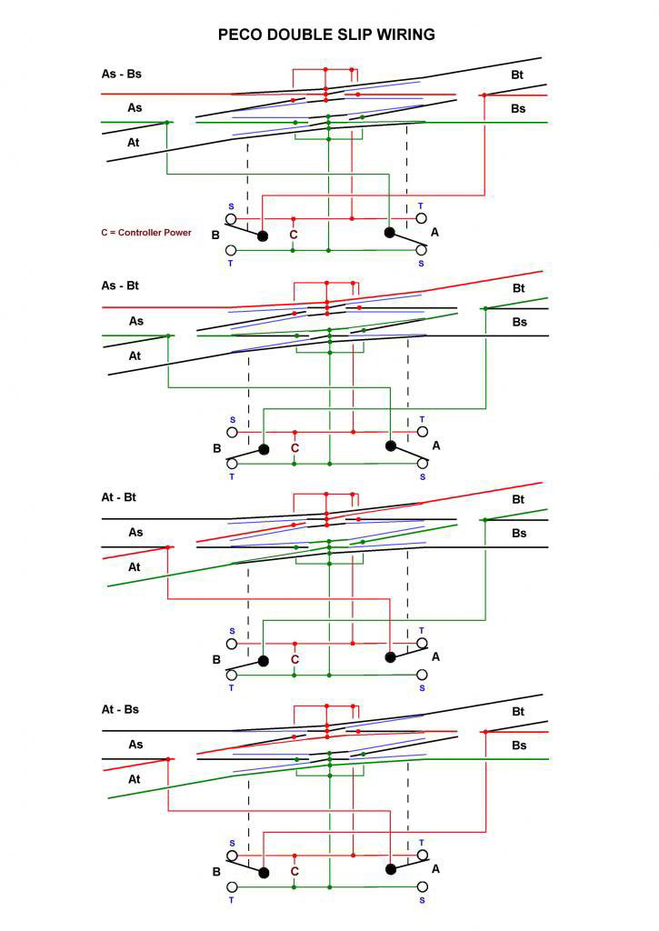
14 March 2014
Here's the wiring for the Peco double slip. I have
one of these in the Evercreech Junction goods siding, and one at the
colliery. This was worked out by my electronics advisor - certainly
not by me!
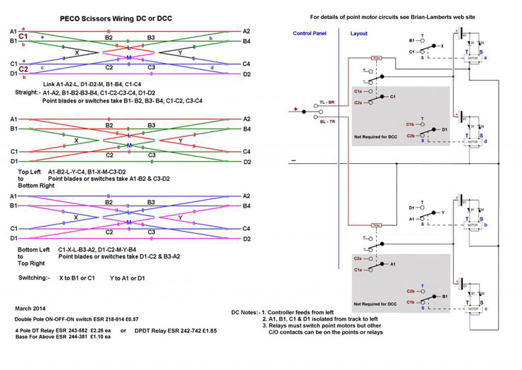
15 March 2014
And here's the scissors crossing at the throat of
Bournemouth West. Don't ask me how it works. It looks like a
spaghetti attack to me.
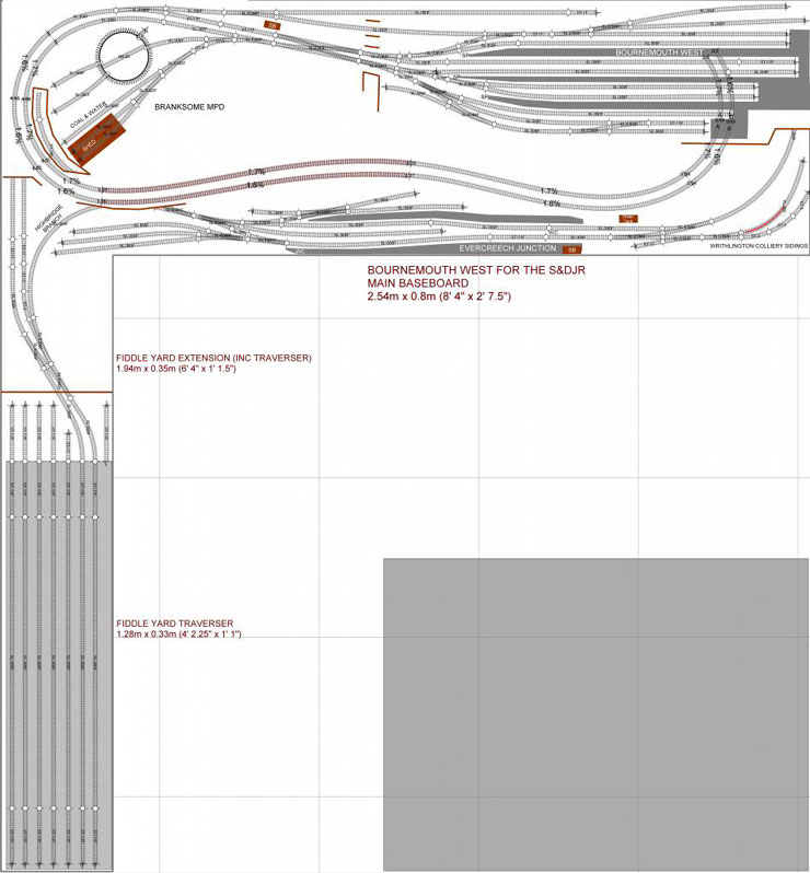
18 August 2014
It's been a while since I posted something here,
but development on the track plan has been ticking along. This is
(probably) the final version, with a large number of minor tweaks
since the last published version. These have mostly been to curve
radii and points positioning, plus some amendments to the MPD. As
before, Bournemouth West is on the upper level, masking the lower
level tracks at the back of the baseboard that connects everything
to the fiddle yard. The incline is now a fairly acceptable 1.70% or
1-in-59.
Again, click on the image to see the full-sized
version.
19 August 2014
As far as the details go in the track plan, I'm
modelling 1930, so the platform numbering is correct (it was swapped
around in 30 September 1931).
I've used the 1909 Ordnance Survey map that's
reproduced in 'Bournemouth to Evercreech Junction' by Vic Mitchell
and Keith Smith, matching my station track plan to that except for
the outermost two goods/storage lines on the northern side of the
station (the Wharf Road side). These were omitted for reasons of
space. The points connecting all the station lines to the approach
road have also been altered where necessary to be able to fit in all
the connections, but they're generally similar if not exactly the
same.
Platform 1 is shown clearly (in its later Platform
6 mode) in Photo 8, with the line next to it being used for carriage
storage. Photo 3 just about shows the goods area beyond these lines
(the online pic 3 also shows this, albeit from the opposite end of
the platform, with the carriage storage line containing some
carriages, then the goods shed line and the two adjacent goods
storage lines - the only line not seen is the outermost one). The
second goods line also has carriages on it, so I'd say that the use
of all of these lines was flexible, even if they were used for goods
wagons much of the time. Admittedly I've restricted myself in terms
of goods storage, but I'll just have to juggle the carriage storage
line when goods needs more temporary storage, so it's a good excuse
for a bit more shunting.
Photo 1 shows the station exterior in 1914 (much
better than the 1962 version for my purposes), and I'll really need
some luck with those chimneys! What I can't work out is when the
ugly sheet steel canopy over my Platform 5 (the later Platform 2)
was built by the SR. I have it there in 1947 but (obviously) not
there in 1910.
The signal box on the track plan is Branksome's
rather than BW's, but again it's on the wrong side - necessary
otherwise it would be sitting with its back to the audience. The
line at the very back of the plan is my substitute for the lost
carriage sidings that lay outside BW itself, but I suppose it could
also substitute the missing Wharf Road line. There's certainly not
the space (or the budget!) for a second scissors crossing. Instead,
the available lines will be used for carriages or goods as the
timetable demands.
The traverser will definitely have a couple of full
length shelves for stock storage, although they won't be connected
to the layout. The layout is more a flavour of BW rather than a
scale representation - impossible in just 2.5 metres of space. The
full title, Bournemouth West for the S&DJR, shows that the main
theme is the S&D (in its very last days of semi-independence), with
operations via Evercreech Junction (again scaled down but still
relatively accurate in what it includes) that can be handled by a
mixture of S&D and LMS locos hauling a mixture of S&D and SR rolling
stock. All of that runs into BW which also has purely SR services
arriving and departing from and to the rest of the country (the
fiddle yard). It should be a pretty busy layout that will give me a
lot of opportunities to run varied locos and stock. Fingers crossed.
27 August 2014
Initial thoughts from DorsetMike on how to achieve
a realistic Bournemouth West Station:
BH Enterprises do some LSWR/SR valancing; the south
facing side of each canopy looks to be almost continuous roof
lights, Scalelink and Peedie do etched skylights, but for the
quantity you require that could get expensive.
I'd be inclined to use plastic sheet, clear on
south side plain on the north, draw in the rooflight framing with
fine paint marker or use thin plastic strip.
As the support girders are fairly well hidden apart
from the ones that go between the platforms I'd suggest having those
visible ones extended from the station building across all platforms
and fix the triangular roof trusses/supports to them, they could
either be built up from plastic section or cur from sheet. The outer
ends cut from plank embossed plastic, valances fixed to the bottom.
The pillars don't show up well in the images, but
are probably tapered round ones, again BHE do a cast LSWR pattern.
They also do fancy etched bits for the tops.
There seems to be only one central row of pillars
for each platform, hence the girders between platforms. I suspect no
pillars on those parts of platforms with buildings; they will have
brackets from the buildings. Not being able to see the top of the
roofs it's difficult to suggest a finish; they could be planked or
panelled. Scalescenes do a panelled paper. Corrugated iron is
another possibility. If you can find a pic showing the edge profile
that might help.
The canopy edges are not corrugated or clear. If
you look at one of the better photos that show it, you can see that
the skylights look more like those that are available from Peedie
Models. Scalelink do a similar item on a longer fret (203mm) and
also do frets that would provide the wall supports for the girders
1 September 2014
Seeing as the layout plan has been finalised. the
construction phase can begin on the next page (click on the link in
the blue bar, below).
Additional input on this page provided by NGF
members Leo1961, DorsetMike, and newportnobby.
|