|
25 February 2014
As a first locomotive kit of any description, the
Paxman Diesel No 10800 resin body by Parkwood Models is an ideal
place to start.
Diesel No 10800 was initially commissioned by the
LMS in 1946, but was only delivered in 1950, to British Railways.
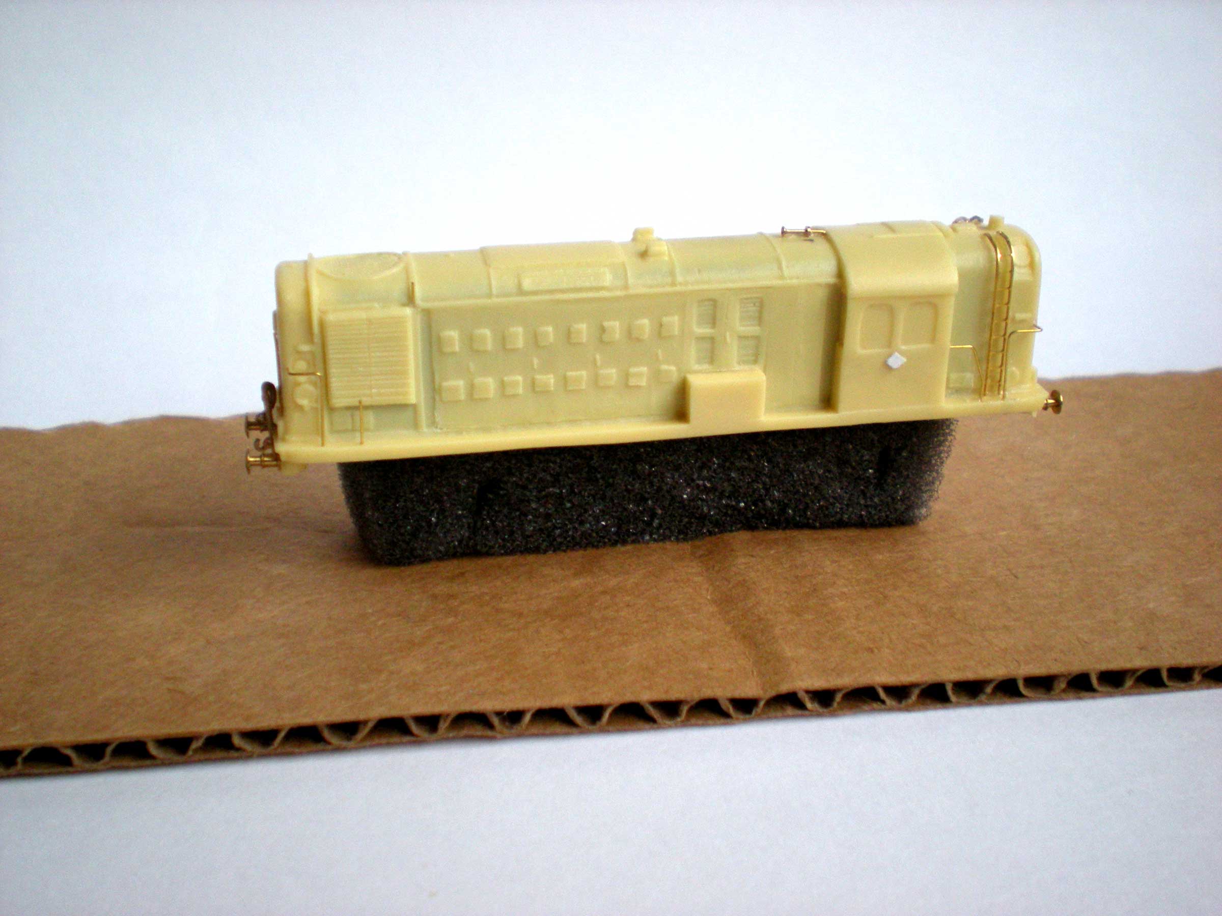
Resin is a very easy medium to work with. It is
soft enough to make drilling small holes for handrails and buffers
very easy, and to make filing off cast details such as an air horn or
ladders relatively simple, just as long as you take your time.
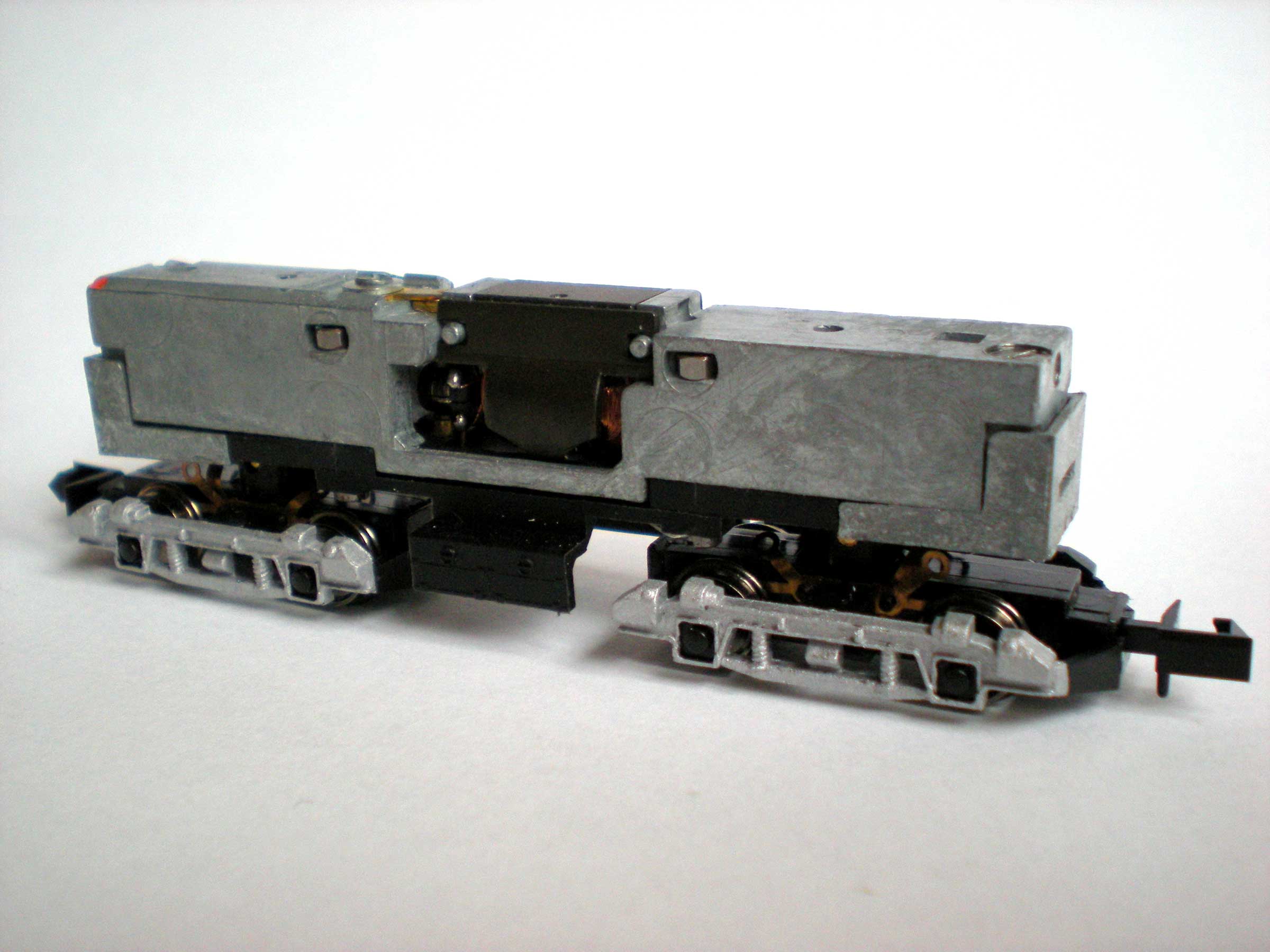
Once you have the resin body, you will also need a
second-hand, Poole-era Graham Farish Class 20 diesel chassis. These
are relatively cheap on second-hand and auction websites. In this
case, the Class 20 in question came with split gears (and a
correspondingly low purchase price!), and these had to be fixed
before the loco would work. See
Replacing Split
Gears on a Farish Class 20 for details.
To begin preparing the resin body, first check that
it fits your chassis. If it doesn't then you may need to file down
parts of the internal shell. Fortunately, in my case the body fitted
perfectly at the first time of asking.
Now give the body a brief soak in warm, soapy
water to clean off any residue and make it ready for undercoating.
To detail the body you will need the following parts:
- Handrail Wire 0.33mm (N Gauge Society TEC002)
- Handrail Wire 1.00mm (I used a makeshift replacement)
- LMS Head Lamp black x 1 (Springside Models SPN4 via eBay)
- Vacuum Pipes 1 Pair (N Brass Locomotives 2058)
- Coupling Hook 1 Pair (N Brass Locomotives 2076)
- Screwlink Coupling 4 Pack - two required (N Brass Locomotives 2201)
- Brass Ladders - optional (CR Signals via eBay)
- LMS Loco Buffer 3mm dia, 4 Pack (N Brass Locomotives 2349)
- Air Horns 3mm, 2 Pack - one required, optional (N Brass Locomotives 2425)
- LMS Loco Graphics 1927-Late 1930s (Fox Transfers FRH2225)
- this is not standard numbering and lettering for this loco, which ordinarily
should bear the early BR crest and the number 10800
You will also need the following tools and paints:
- Pin Vice Revolving Top 4 Jaw (Gaugemaster GM624)
- Micro Box Drills 0.3-1.6mm (Gaugemaster GM648)
- Needle Files - Set of 10 (Gaugemaster GM632)
- Micro Flat Clear Finish for Models (or similar matt varnish) (Microscale)
- Micro Glaze 1 fl oz (Judkins via eBay)
- Gun Metal acrylic paint (Tamiya X-10)
- No 1 Grey Primer Spray Matt (Humbrol AD6001)
- RC401 Dirty Black matt acrylic (Humbrol AB2401)
- No 174 Signal Red Satin Acrylic (Humbrol AB0174)
- No 35 Gloss Varnish (Humbrol AB0035)
- No 11 Silver Matt Enamel (Humbrol AA0120)
- Frame Dirt Acrylic (Railmatch 2402)
- Oily Steel Acrylic (Railmatch 2415)
Plus you'll need the usual paint brushes, thinners,
craft knife, superglue, etc.
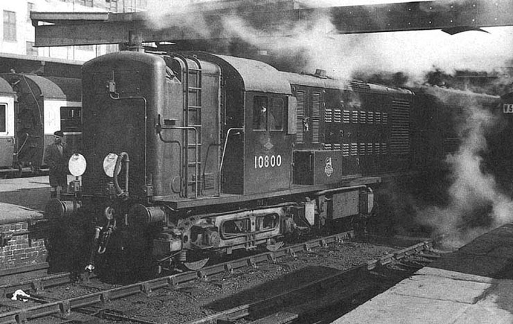
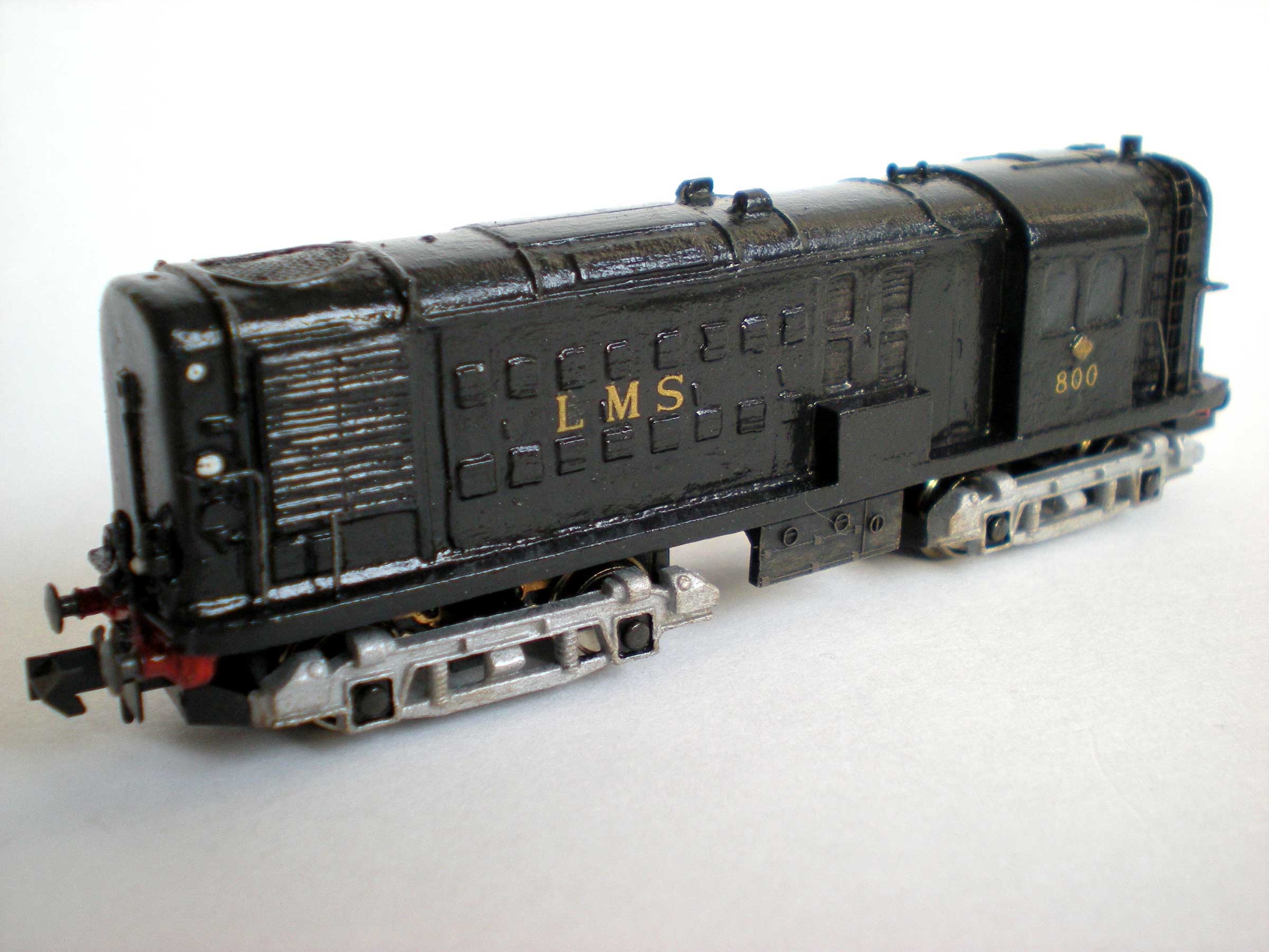
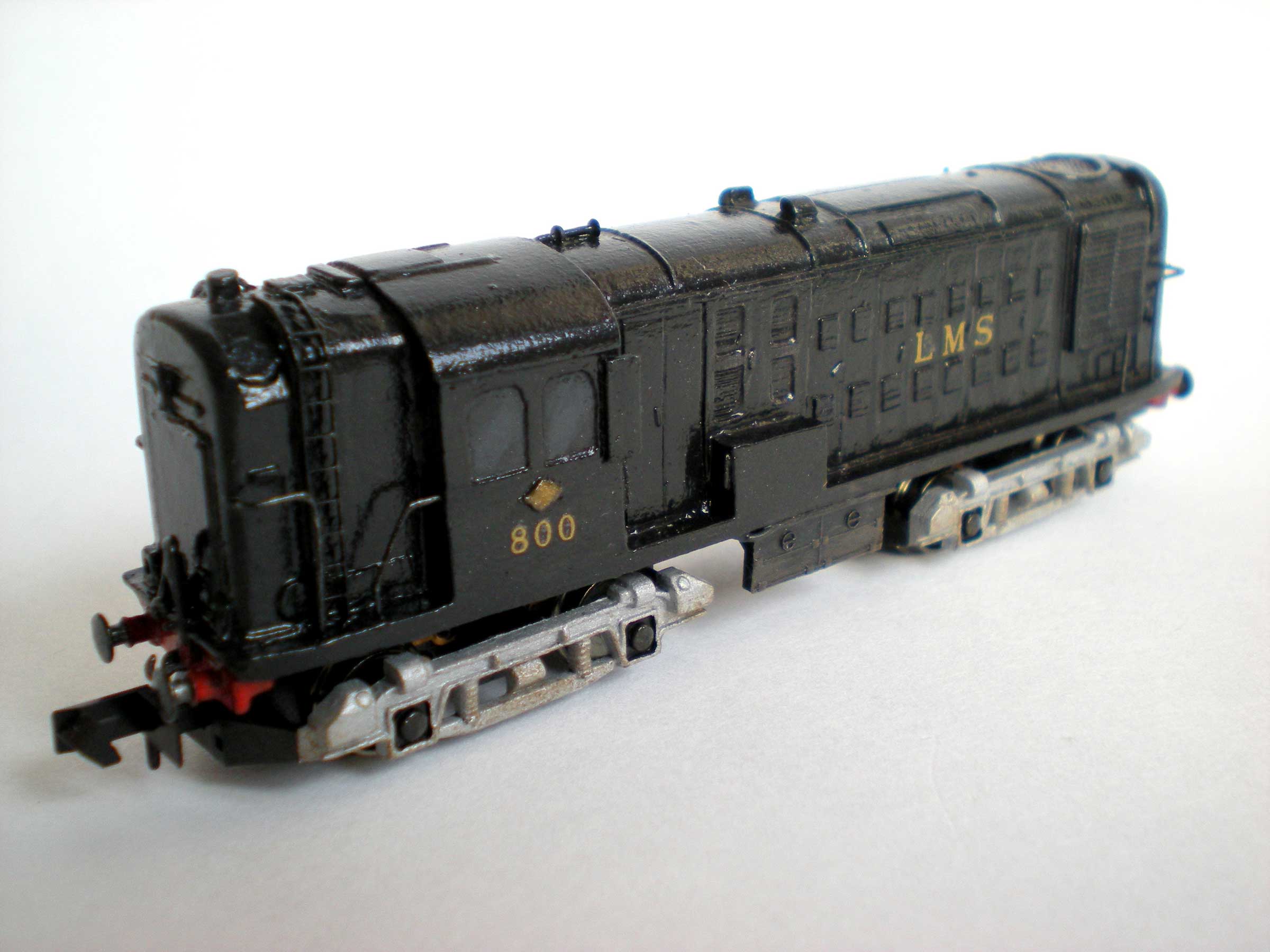
Before doing anything else, do a little
research. Above all, find some photos of Diesel 10800. It was
commissioned by the LMS in 1946, as No 800, and would have entered
service with LMS lettering had it been delivered a little more
quickly.
As it was, Nationalisation took place in
1948 and the loco was delivered in 1950. As a prototype its
performance was understandably erratic, and it was eventually
withdrawn from service after a decade.
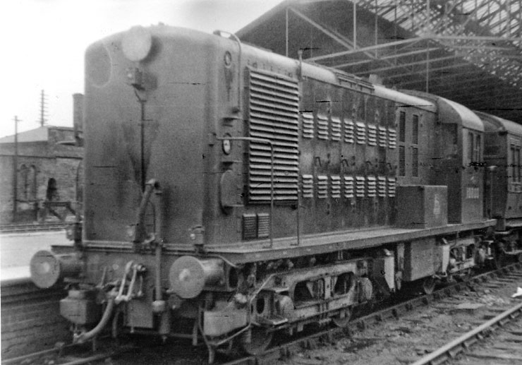
No amount of text will give you as much valuable information
as a few photos, though. This, and the example at the top of the page,
are two of the better ones.
Body preparation
Start by using the pin vice and drill bit to gently
drill out the front and back buffer holes until each buffer will fit
inside snugly. The holes have already been started for you as part of
the resin mould.
With my local model shop out of stock when it came
to a full set of drill bits, I could only get an 0.3mm drill bit for
the work. Using this very carefully - as they're pretty fragile things -
I drilled an initial hole, and then used a metal needle file with a rounded
tip to open it up a little and then the drill again to widen the deeper
hole and file a few more bits from around the edges until the buffers
fitted.
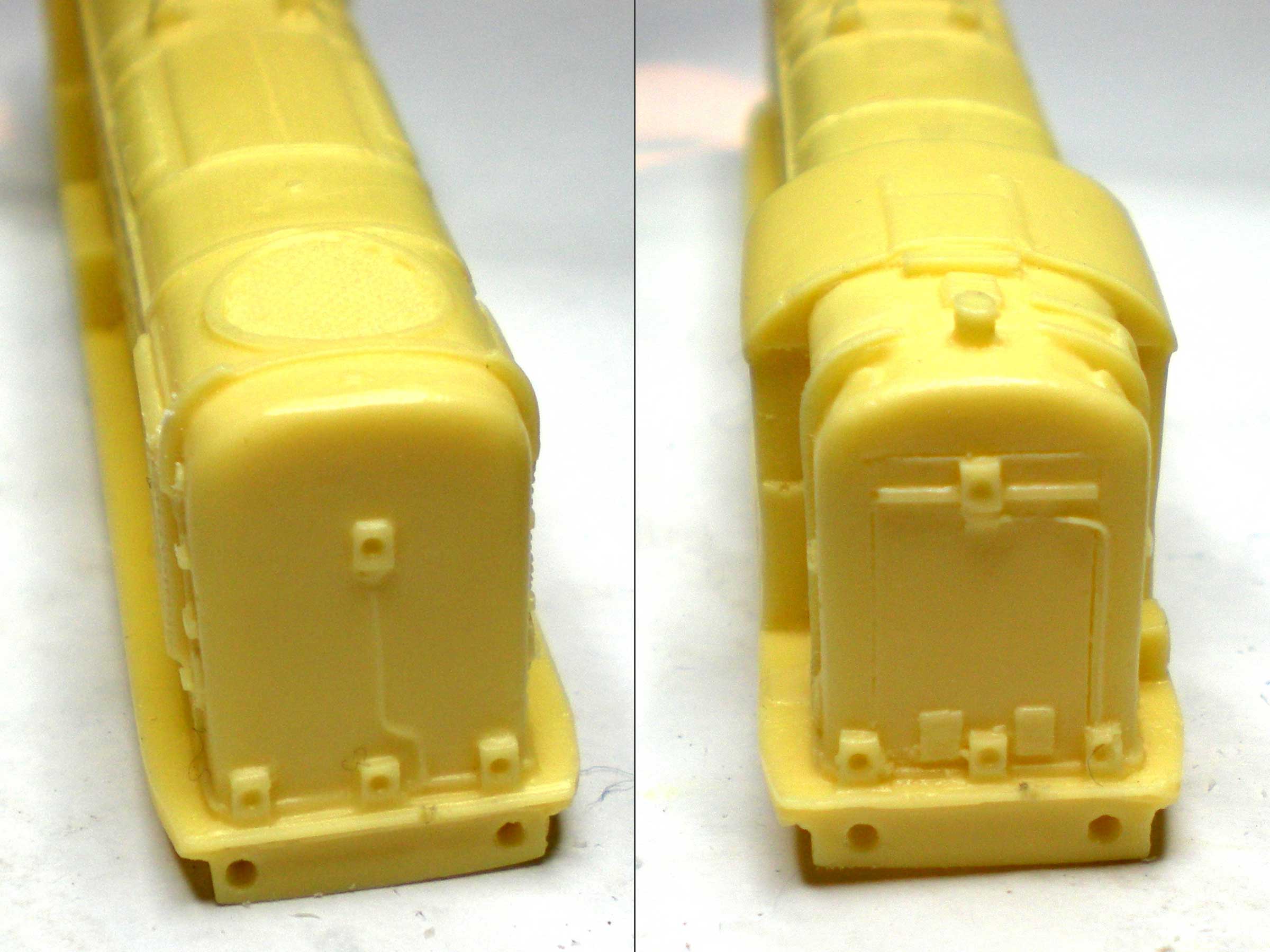
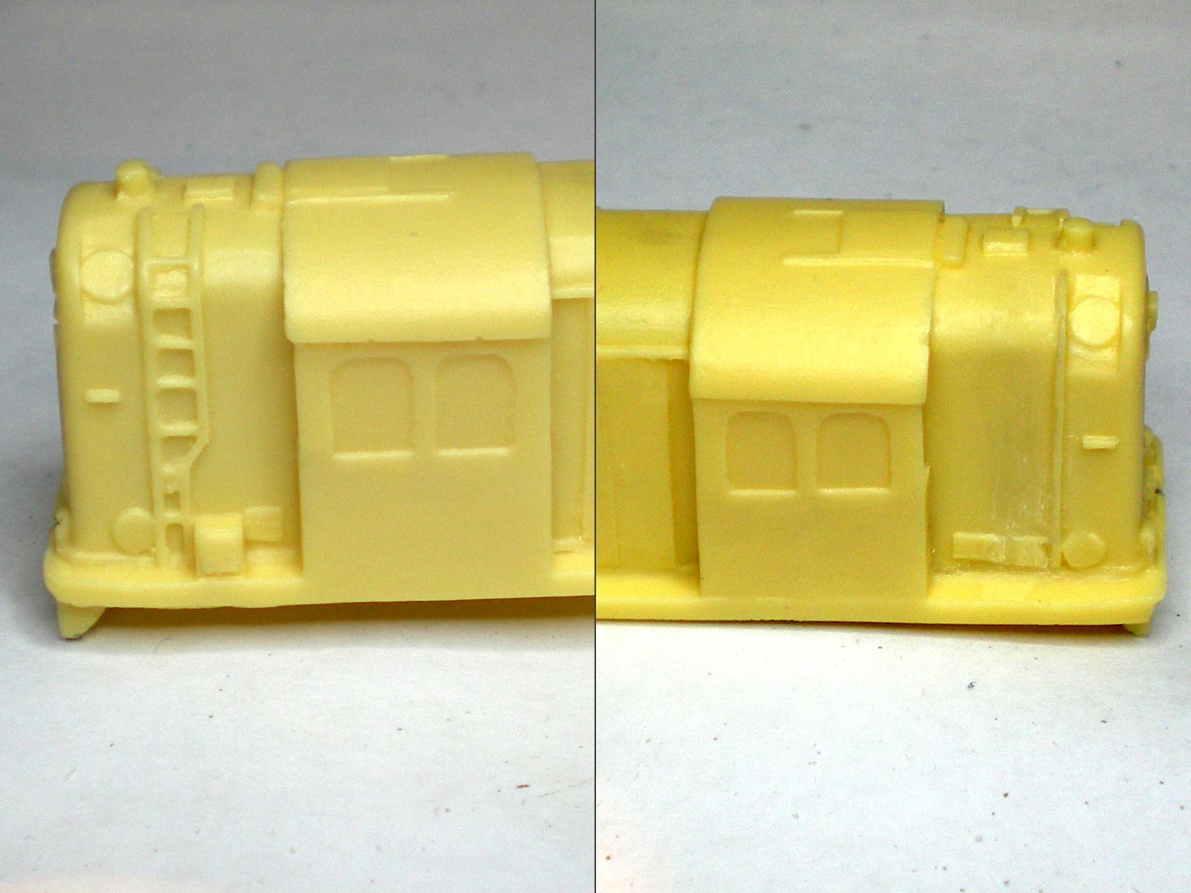
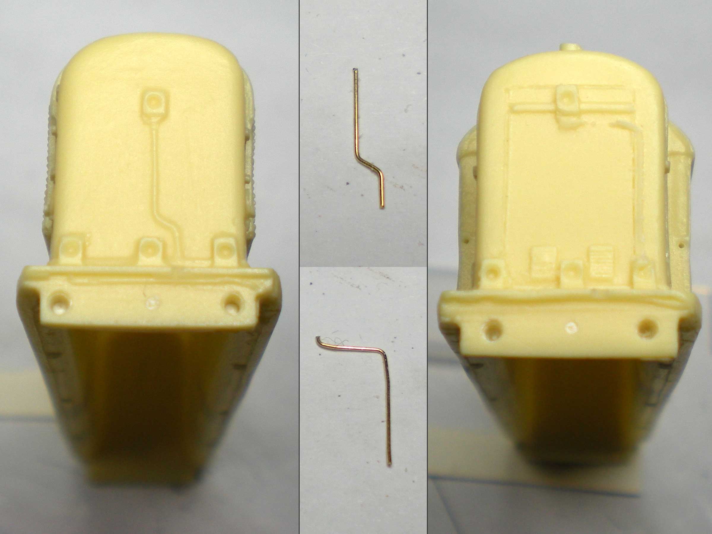
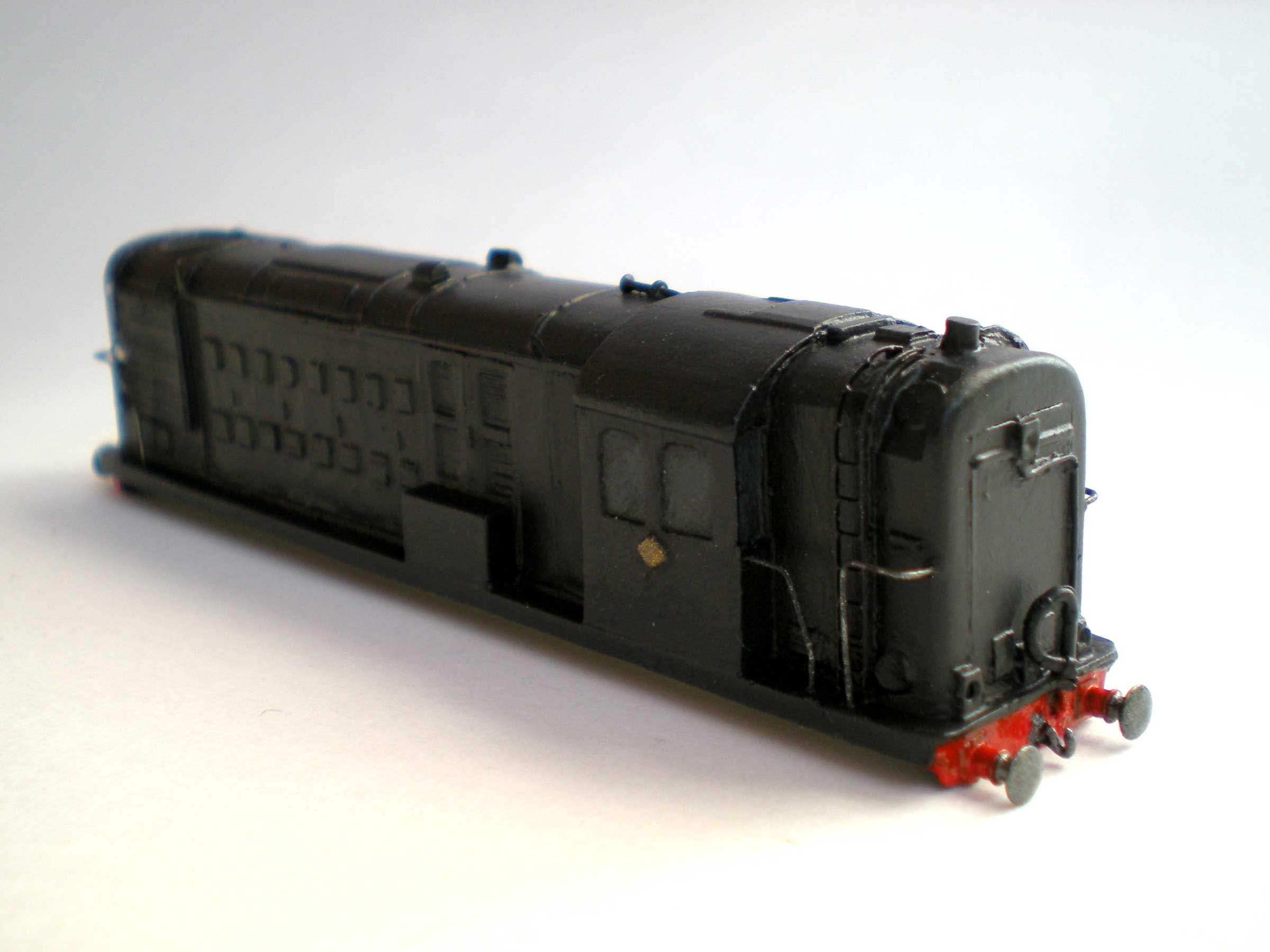
The widened buffer slots can be seen here, with the
front of the loco on the left and the rear on the right:
Next came the resin air horn.
This stage is optional, but a fitted brass air horn
will look a great deal better than the roughly moulded version that
comes with the body.
Select a broad file and gently smooth this down to
the bodywork. Take your time and take it off in small doses so that
you don't bite into the bodywork itself. It takes just a couple of
minutes to do it properly. Now the space is clear for a brass air horn
to be attached later:
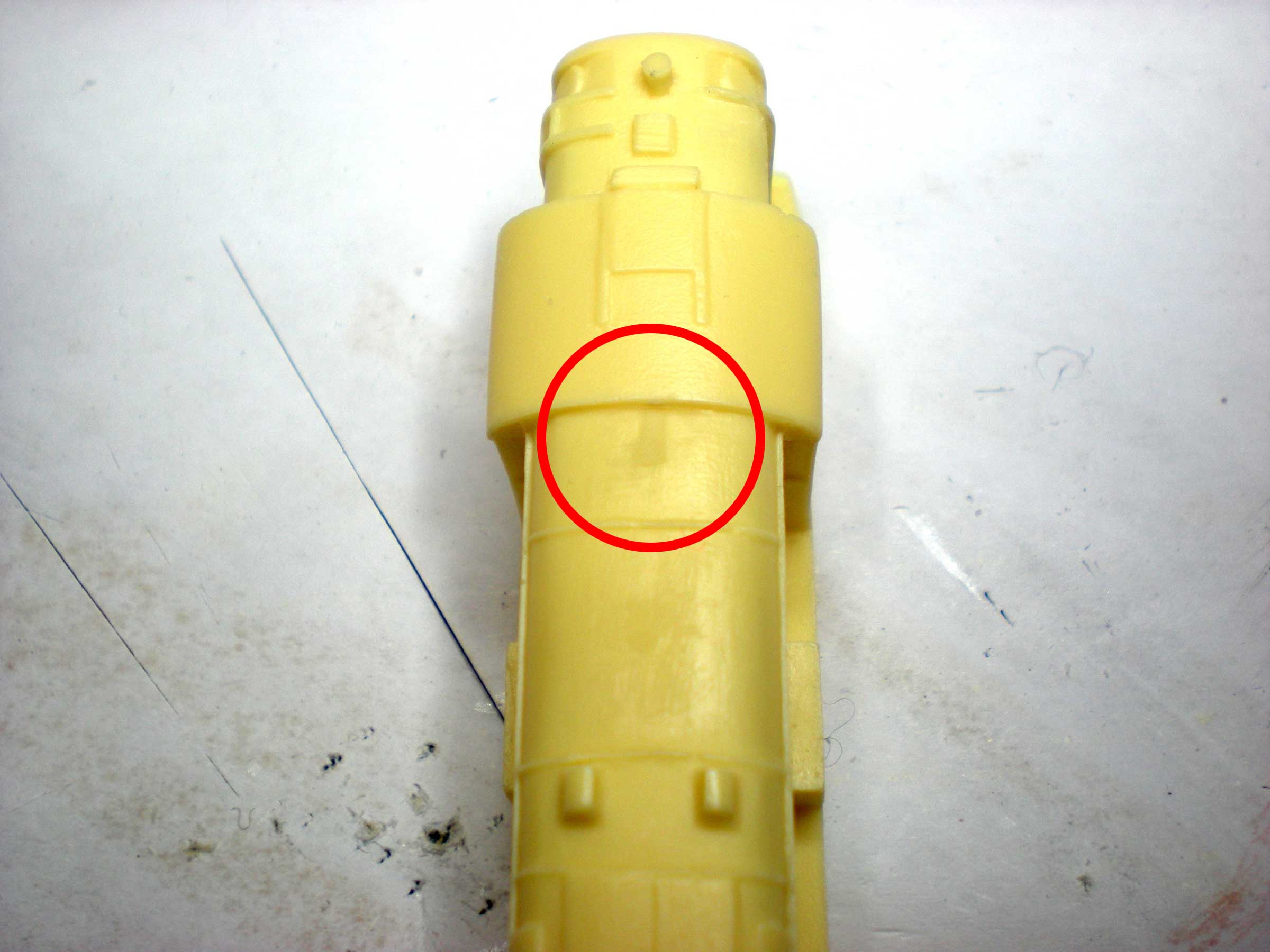
Immediately below the red circle in the photo above,
on the next roof panel on the loco, there may be the stub of a moulding
sprue. This also needs to be filed smooth.
Another optional adjustment concerns the ladders
behind the cab.
Many photos of the original locomotive in service show
these to be narrowed near the running boards, with a large box squeezed
in beside them. Given that the loco had only a ten year working lifetime,
there aren't too many photos of it in service at all, but a few are
available on the internet. These show it in enough detail to be sure
about the ladders.
Those photos that show the loco in its early days
don't show this box, and the ladders are normal, with no narrowing
at the base. The first photo of the prototype loco, above, shows
it in its earlier condition, but the resin body shows the later
details.
As I'm aiming for the early version, the box had to
be cut out and the ladders too. The photo below shows this before
(left) and after (right), although I left one vertical rail of the
ladder in place to act as a support for the new CR Signals brass
ladder I'd be using. These ladders are a little narrower than
required, and the brass is somewhat delicate, but you can get a very
close approximation of the real ladder by cutting out the top two
rungs and bending the brass over the resin body to fit.
Be careful when filing off the resin ladders to
ensure that you only take off the minimum amount of detail. The
resin body is pretty thin at this point and over-enthusiasm with
the file could easily take you straight through it:
The next step is to create the various handrails
that need to be installed around the loco's running plate. I used
0.33mm handrail wire from the N Gauge Society shop for this (TEC002),
but it seems a little flimsy and delicate, so I'm sure you could
get away with using the next size up.
Measure each length carefully, using a gel pen or
marker to place a dot on the wire where it needs to be bent. Add a
millimetre or two to the length at either end so that you can sink
the handrail into the running plate at the bottom and into the
bodywork at the top.
The instruction sheet tells you the lengths you
need, and I bent mine by holding it against a plastic ruler and
using the rounded edges of the ruler to create a rounded curve on
the wire. If this seems too fiddly, a small vice will help.
Then I drilled a hole in the running plate at the
correct location for the rear railings (or as near as I could get)
- about a millimetre behind the surviving ladder rail, going all
the way through so that the extra length of the wire had enough
room for manoeuvre.
The rear railings are shown in place here, although
the bodywork holes need to be drilled a little deeper so that the
railings can stand fully upright:
Two more railings go on the other side of the ladders,
one on either side, and the shape of these also seems to depend on
whether you're modelling an early or late version of the loco.
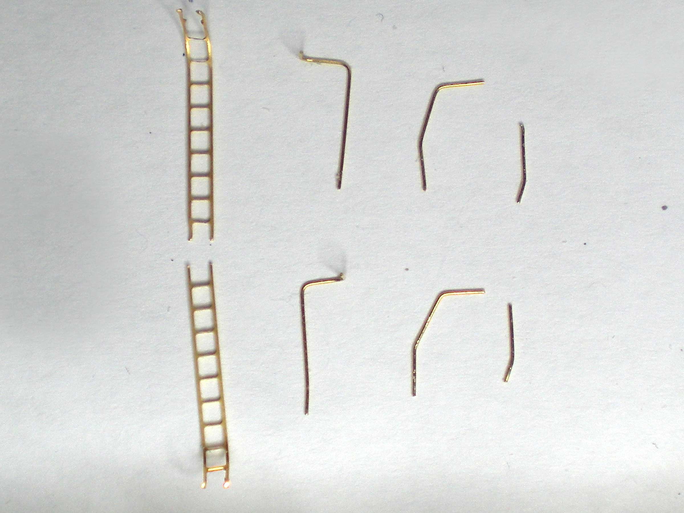
If it's the late version, then the Parkwood Models
instructions should be followed. For the early version, you need two
bends in each handrail to produce the shaped effect shown below.
Allow an extra millimetre or so at each end for
bedding into the locomotive's running plate (bottom) and body (top -
immediately below the cab's rear window). Place the bends at 3mm up
from the running plate (not from the bottom of the handrail, as you
may have cut more excess). Place the second bend 5mm further up the
handrail. Test fit it to make sure you have the correct angles. The
new handrails are shown second from the right:
Next is the stanchion on either side, close to the
front of the loco. A simple 5mm length of visible handrail is needed
on either side (plus a millimetre or so to bed into the running plate).
The slight bend at the bottom of each stanchion is due to the fact
that I had to drill into the running plate at an angle.
There should also be a small 2mm length of 'handrail'
attached to the roof on the left-hand side of the loco, and a small
handle attached to the rear panel of the running plate box, on the
loco's right-hand side.
On the same side, the front of the cab also has a
handrail, about 3mm in length. These tiny handrails can be extremely
fiddly, so do the bending first, allowing a longer than usual waste
length on each bend that you can cut off after you are sure that the
length of the visible handrail is correct.
Then there are the front handrails, made to exactly
the same dimensions as the rear handrails, plus the long handrail on
the cab's front panel, on the right-hand side.
Lastly, perhaps, the original loco had pipes at the
front and rear that look very indistinct on the resin body. These can
also be replaced with handrail material, and replicating the bends in
them is pretty straightforward.
Give the resin versions a very faint filing down to
take the bulk out of the pipes. The remainder will not only serve as
a guide for gluing your replacements in place, but will also help
them to stand out more realistically.
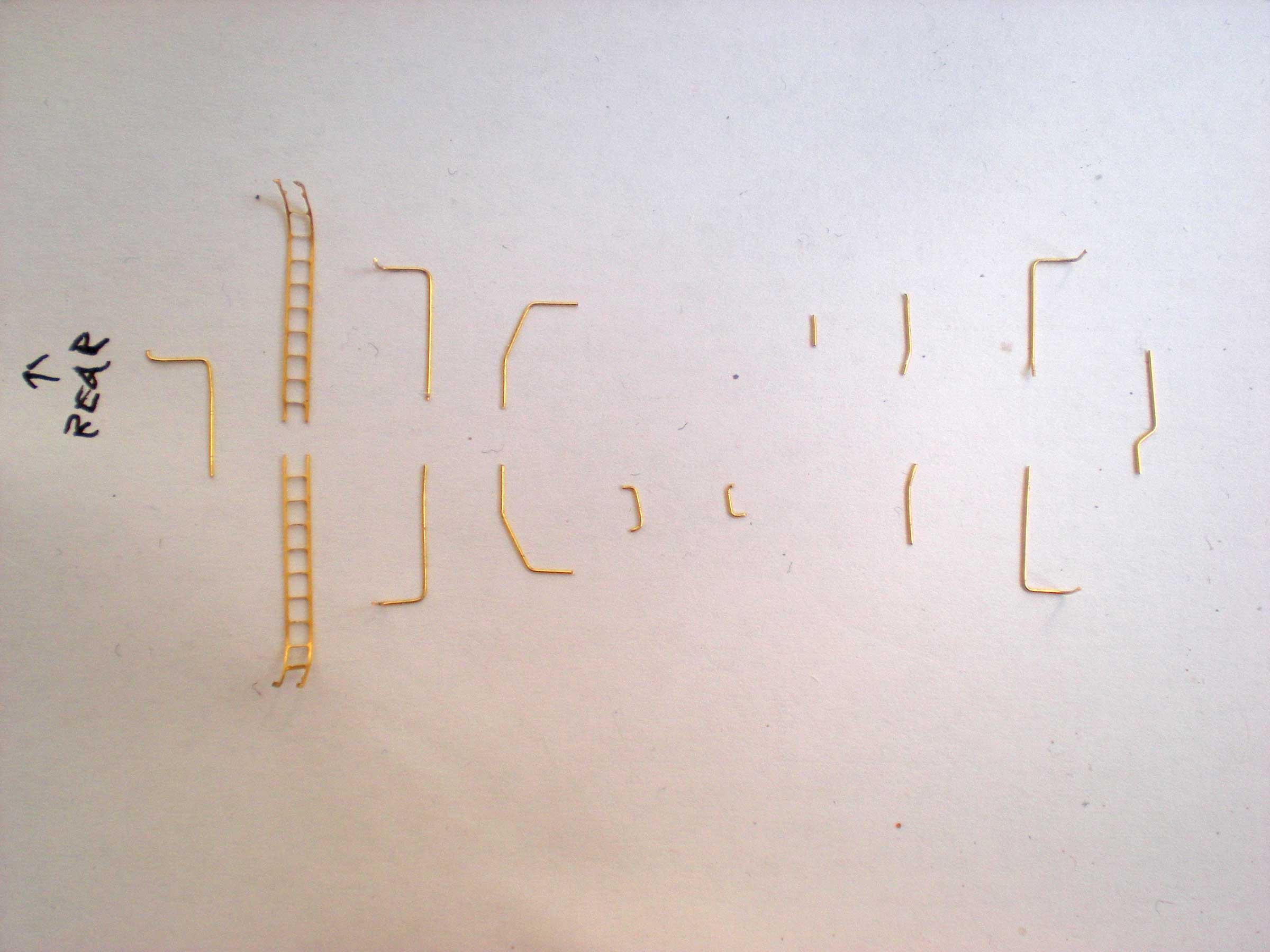
Finally you should end up with fifteen pieces of
handrail wire, all moulded into the correct shapes and ready to glue
to the resin body.
You may also want to attach the hinged panel that
can be seen on the front corner of the loco's cab - on either side
of the loco. This appears to be a sun blind that could be used to
prevent glare on the cab's front windows, so the side of the loco on
which it is installed is entirely up to you.
The Parkwood instructions show that this should be
a piece of plasticard that's 2.5 x 6mm in size, with the two
forward-facing corners slightly rounded. This seems to work about
right.
On the loco's offside (the right-hand side when facing
forwards) there should be a pipe underneath the body between the wheels,
above the chassis details. A piece of 4-5mm wire will be fine for this -
I stripped the plastic off a food tie for this, and spent some time
shaping the metal wire to match the prototype. Glue this to the
underside of the resin body, not the chassis, so that all added
parts remain part of the body. It also makes it easier to remove the
body for chassis and motor maintenance in the future.
Now it's time to attach all the other parts.
But for getting my hands on a copy of NGS Journal
5/96, almost at the last second, I wouldn't have realised that the
rear resin buffer bar doesn't entirely clear the Class 20 chassis.
That issue of the Journal reviews the resin body and mentions the
fact that some of the rear buffer bar needs to be taken away. I
used a square needle file for this, taking care not to damage the
visible buffer bar, and also filed down part of the plastic chassis
where it houses the coupler. The last stage is much the easiest,
so I'd recommend doing this first.
Do the next stages slowly and carefully,
one part at a time. Use a cocktail stick to apply the glue, although
even then some parts - such as the front and rear pipes - may be
problematical to attach. Don't be afraid of peeling a part off,
scraping away the dried glue with the tip of a craft knife, and
starting again.
Having to attend to the buffer beam clearance
problem meant that several bits that had been glued on
managed to fall off. I wasn't entirely happy with the sticking
ability of the superglue, so I started mixing it with Bostik.
Everything is now being attached by placing on a little dab of
Bostik, followed by a dab of superglue over the top of it. This
seems to add more strength to the process - although be warned that
it doesn't set properly for quite some time.
Installing the coupling hooks should mean an
overnight drying time. These don't have plugs or inserts so that
they can be more securely attached to the loco body, so you
definitely want to be sure the glue has dried before you do anything
else. An overnight is also a good idea for the front and rear
pipework and vacuum pipes.
Optional screwlink couplings can be added
to the coupling hooks front and back once the glue on the hooks has
dried. If you're retaining the Rapido couplers then you'll need to
fold up the screwlink couplings so that they don't foul the Rapido.
This seems to be entirely prototypical anyway, so it's perfectly
acceptable. It seems to be best to leave this stage until after
painting, otherwise you'll obscure the buffer beams. The same goes
for head lamps.
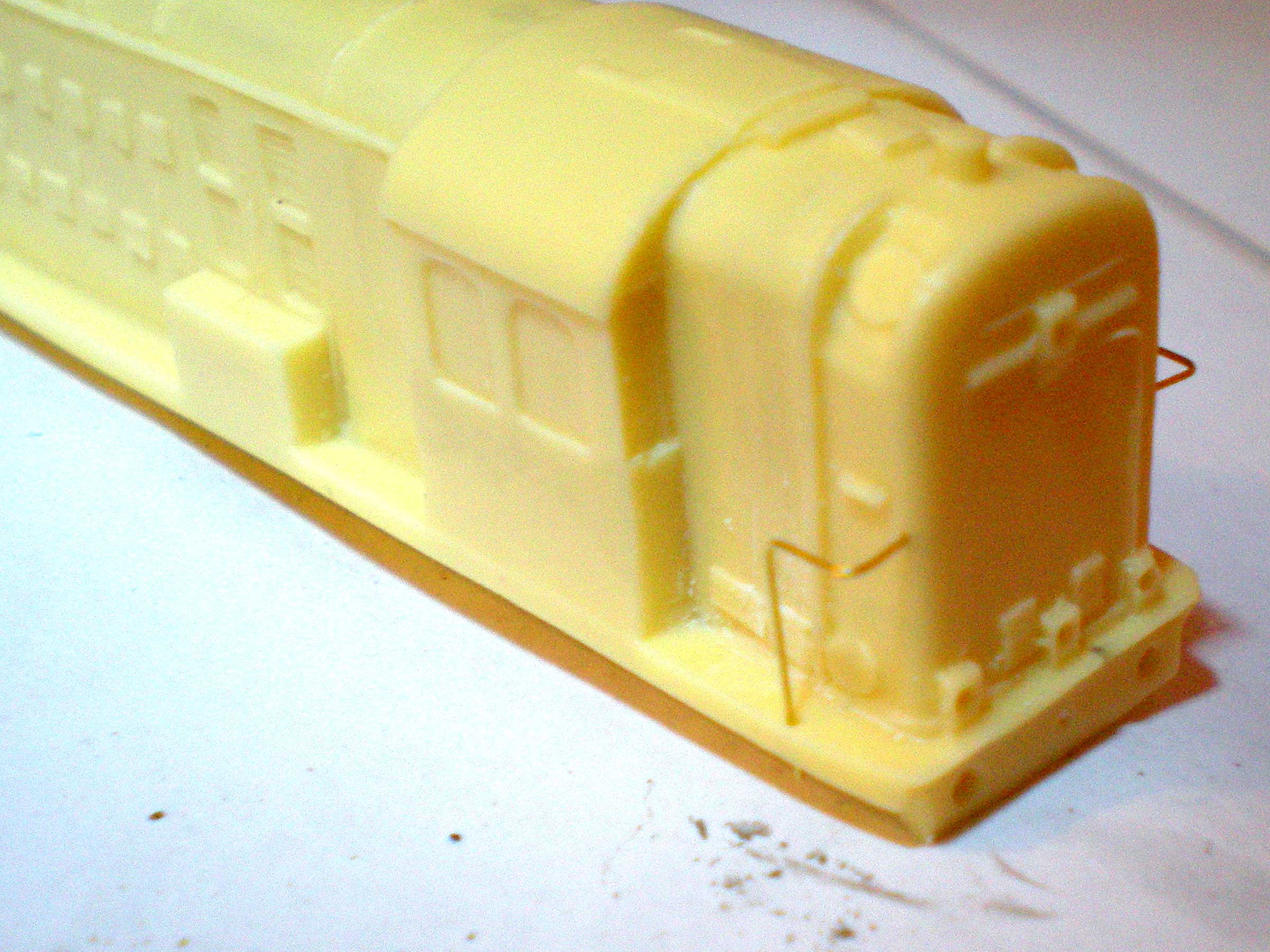
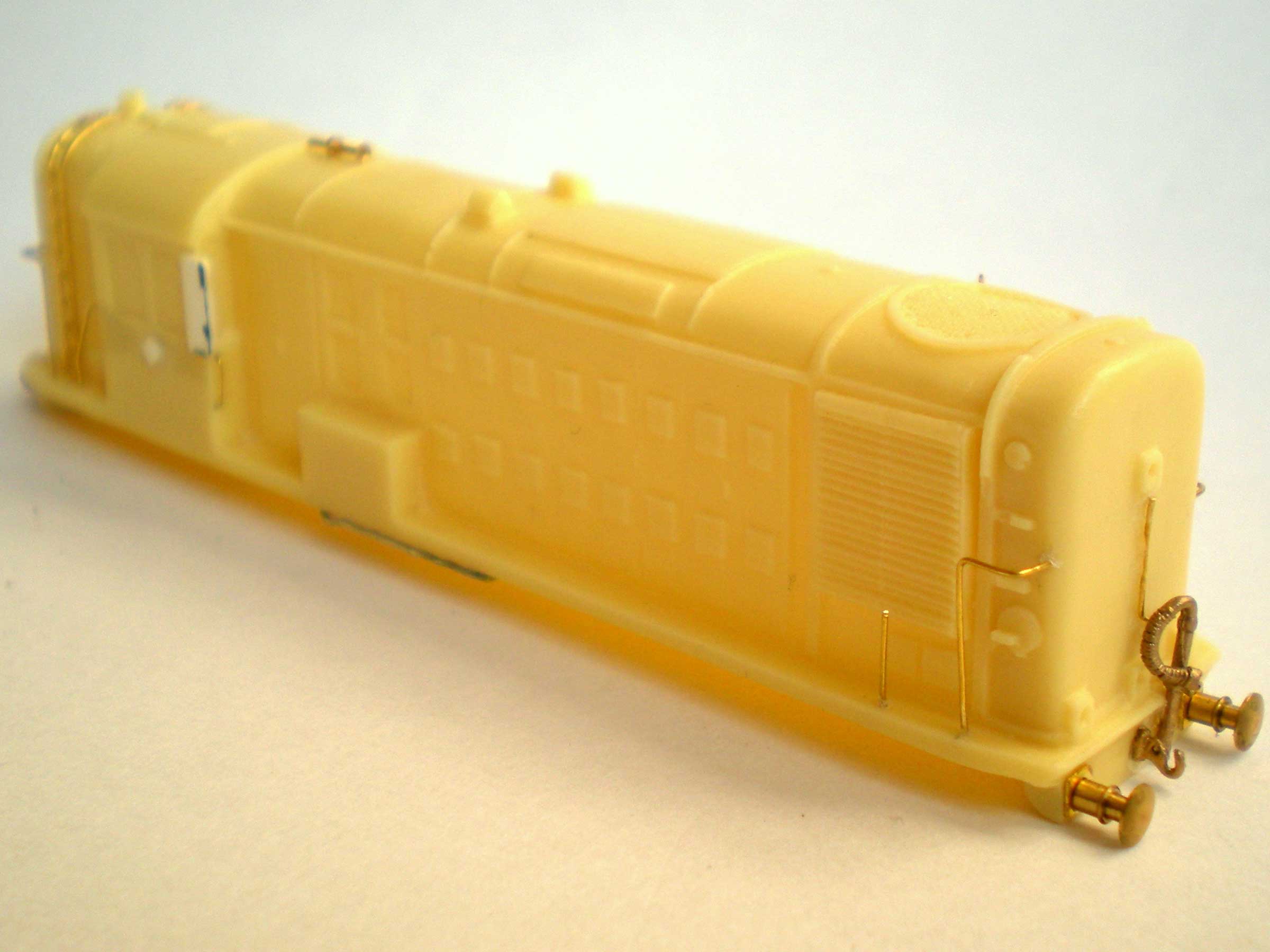
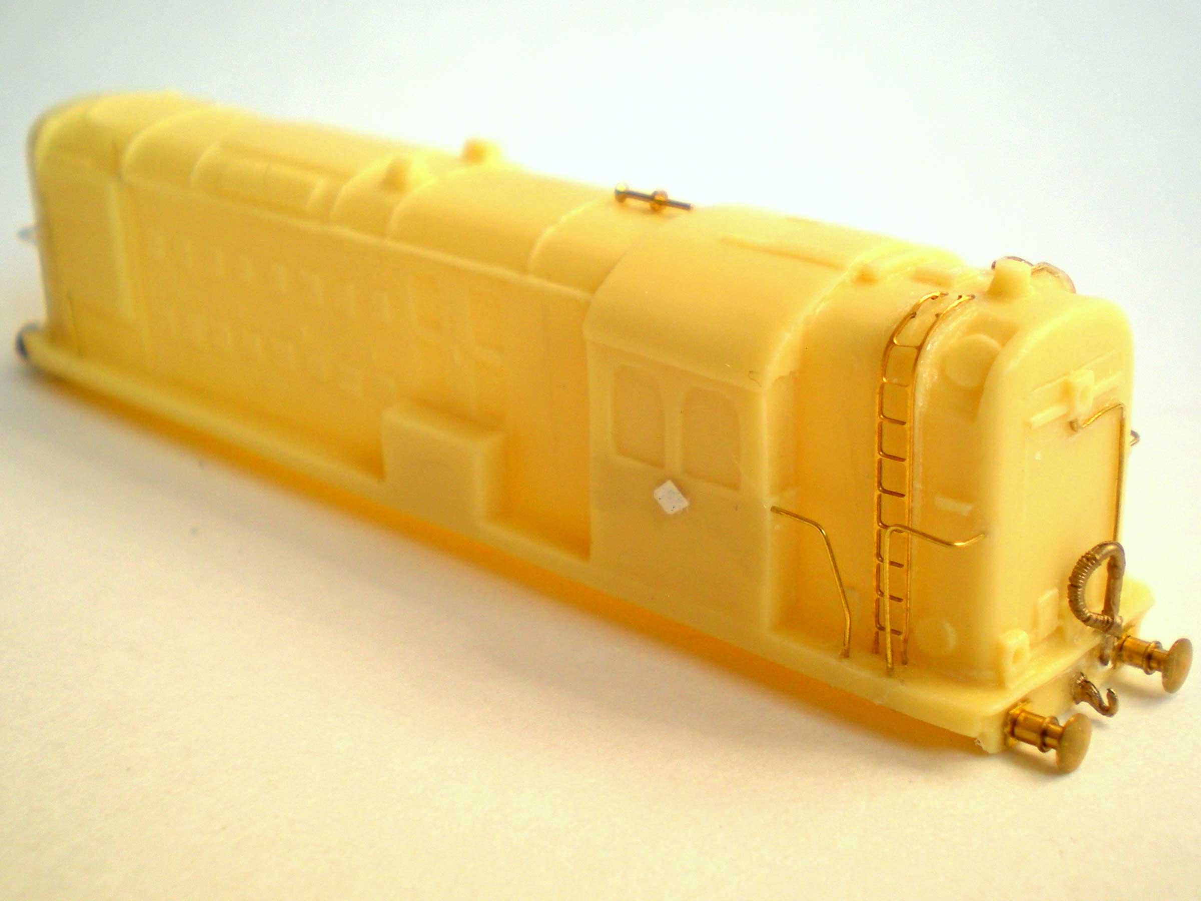
Here's the resin body with all pre-painting parts
attached (and hopefully staying there):
I spoke too soon, of course. The last piece to
be attached, the air horn in front of the cab, simply fell off
less than twenty-four hours after appearing to be attached. To
make it more secure before gluing again, I drilled out a small
hole at the front of the cab (it stands very slightly above the
main roof). I also lightly drilled out parts of the resin
underneath the spot where the horn's central rim would sit, so
that it could be embedded very slightly into the roof, making it
more secure.
Again, the re-glued air horn was left for twenty
four hours so that it could dry and decide not to fall off.
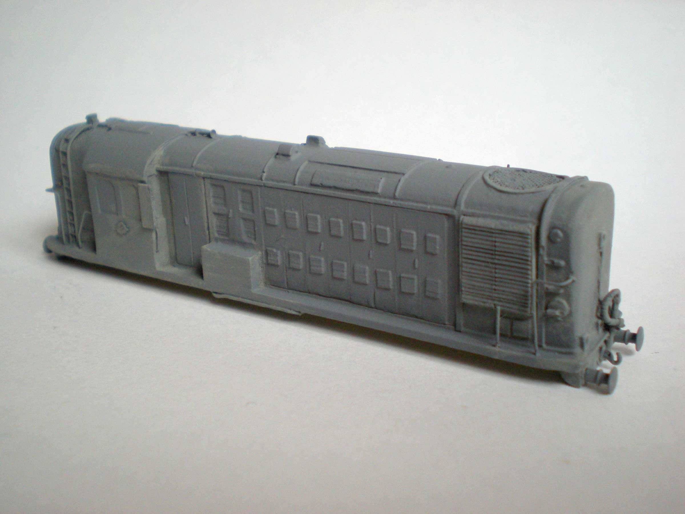
Once the glue has fully dried, you have a complete
loco body that can be undercoated (in this case using Humbrol No 1
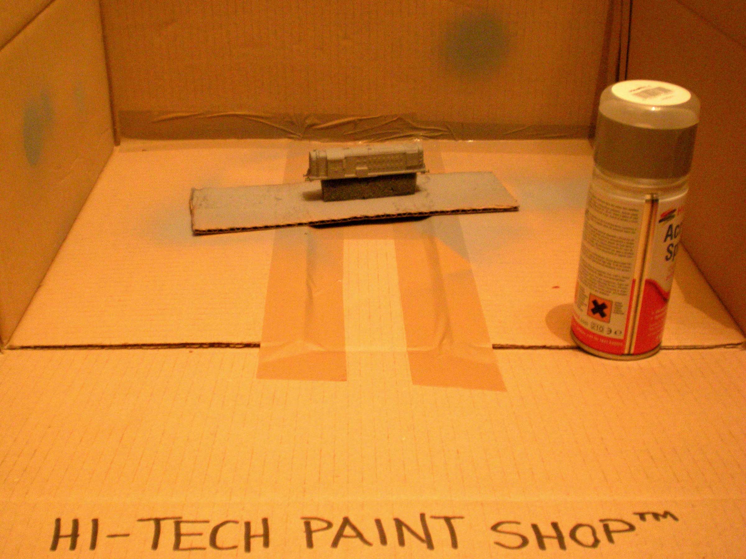
Grey Primer aerosol spray for ease of covering).
I created a dedicated spray mounting stand with a
large slab of thick card, a chunk of foam, and two netting hooks
pushed up through the card into the foam to hold it steady.
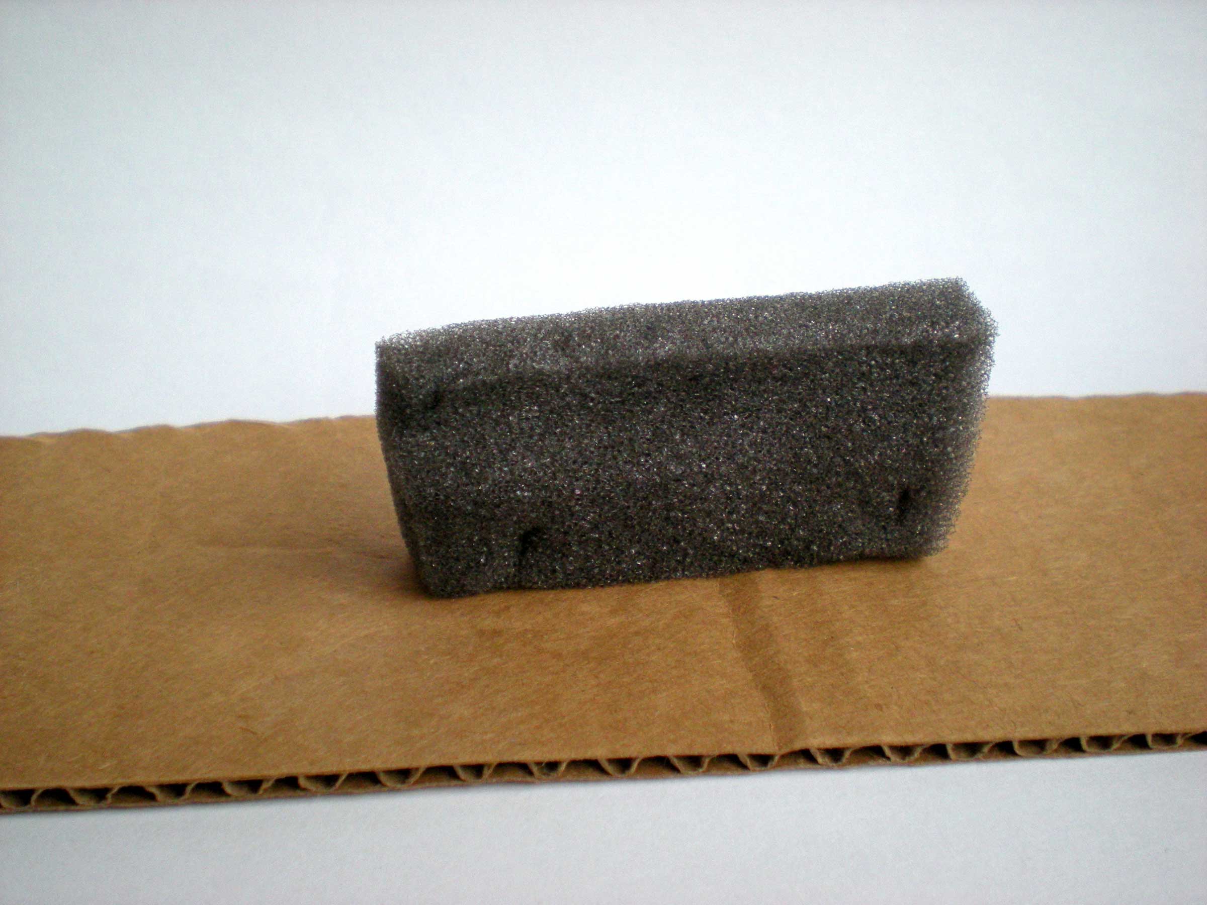
Slide on the resin body, and you have a safe and
secure way of holding it steady while you spray on the primer:
My Heath Robinson 'spray studio' was a cardboard
packing box with the lid secured in the raised position at the back
and sides and with the front panel opened up as a tray to allow the
maximum spray area while preventing the house from being undercoated
too.
Use packing or masking tape to cover any gaps around
the edges in order to prevent paint from leaching out:
Spray on a thin coat, starting off well away from
the body and moving the can quickly along the body itself. Stop
spraying after you have completed a pass along the body and have
cleared it fully.
A second coat is also a good idea. Make sure you
don't have any gaps (although if you do, it may be easier to touch
these up with a paintbrush rather than more spray).
Now it's time for the top coat. I'm using RC401
Humbrol Dirty Black Matt Acrylic for the body, mixed with the merest
hint of white to lighten it a tad.
The handrails can all be painted black for ease but
I'm overpainting them with a black/dark iron mix to give them some
differentiation from the bodywork.
The cab windows can be painted black to start with.
Then wash them with a heavily-thinned white, and dry-brush some
light grey in a kind of broad strip to indicate light reflections.
Finally, coat two or three times with Judikins Micro Glaze for a
hazy reflective window effect.
Two dials on the left-hand size of the nose (when
looking forwards) need to be painted white. If you can keep a very
steady hand, try adding a dial centre or marker on top of that.
The buffer beams need to be painted red, but Humbrol
RC406 Buffer Beam Red seems to come out with a magenta hue, even when
painted onto a white undercoat. Instead I used Humbrol 174 Signal
Red Satin Acrylic. This seems to be very thick, however, so it needs
mixing with thinners until it can be spread smoothly. Make sure the
undercoat is white (or even Buffer Beam Red if you already have it),
otherwise you'll need three coats to cover the black.
The buffers and buffer shanks are Tamiya Gun Metal,
as is the coupling hook. The vacuum pipes are black, but the part of
the vacuum pipes that masks the buffer beam should be red.
The lozenge panel under the cab windows should be
painted in something suitable. I used Humbrol 54 Brass Enamel
Metallic.
The air horn on the roof is black, preferably a
little shiny. Either paint with black enamel or give it a dab of
gloss varnish when finished.
That's it with basic painting of the body.
The chassis frames need to be picked out in Humbrol
11 Silver Metal Enamel. Acrylics here won't really do the job as well
because the plastic on the frames is of a 'greasy' type that will
affect coverage. Coverage with the silver enamel is good, but slow.
I did one side of the loco per night.
If you have screwlink couplings to add to the coupling
hook, these can be painted separately and added now. To keep it clear
of the front coupling hook, I bent mine in half and attached the loose
half to the vacuum pipe.
Then give the loco body two or three coats of
varnish. I'm using gloss to replicate the loco's shiny out-of-the
box look, but will dull this down in places later.
Then add the decals of your choice. In BR days
the loco number went underneath the cab windows while the lion
emblem went on the box amidships. I went for something slightly
different, using Fox Transfers to show the loco under LMS ownership
(which was scheduled to happen, with it being numbered as loco 800.
Only late delivery got in the way of this).
Seal the transfers with a couple of thin coats of
gloss varnish, and then a matt varnish layer if required. As my loco
is fresh from the manufacturers, I'm leaving it with a gloss shine.
Next is weathering and final touches. Several
photos show the loco with a lamp mounted on the lower left-hand
corner of the nose (when looking forwards). One was glued in place,
a black lamp, as the white version never seems to have been used
with this loco.
A light drybrushing of Railmatch Oily Steel around
items such as coupling hooks is also a good touch. I also dry-brushed
this colour over the vents and then washed them with a 50/50 black/thinner
to give them a bit more depth.
The main exhaust vent is the round shape at the very
back of the roof. Try and add some drybrushed dirtying around it.
Once you've done, varnish again, either gloss or
matt, remembering to give the chassis frames a couple of coats at
the same time, if you haven't already done so.
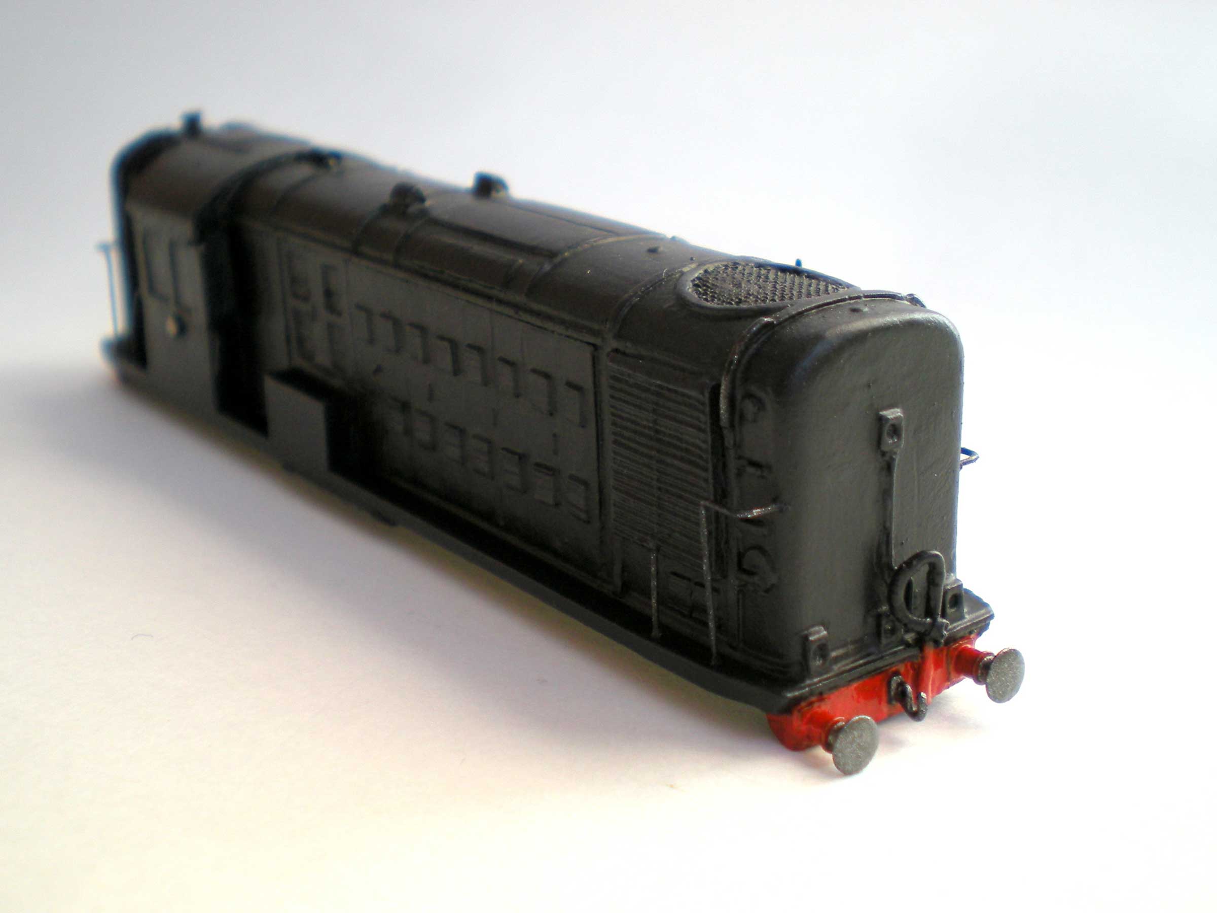
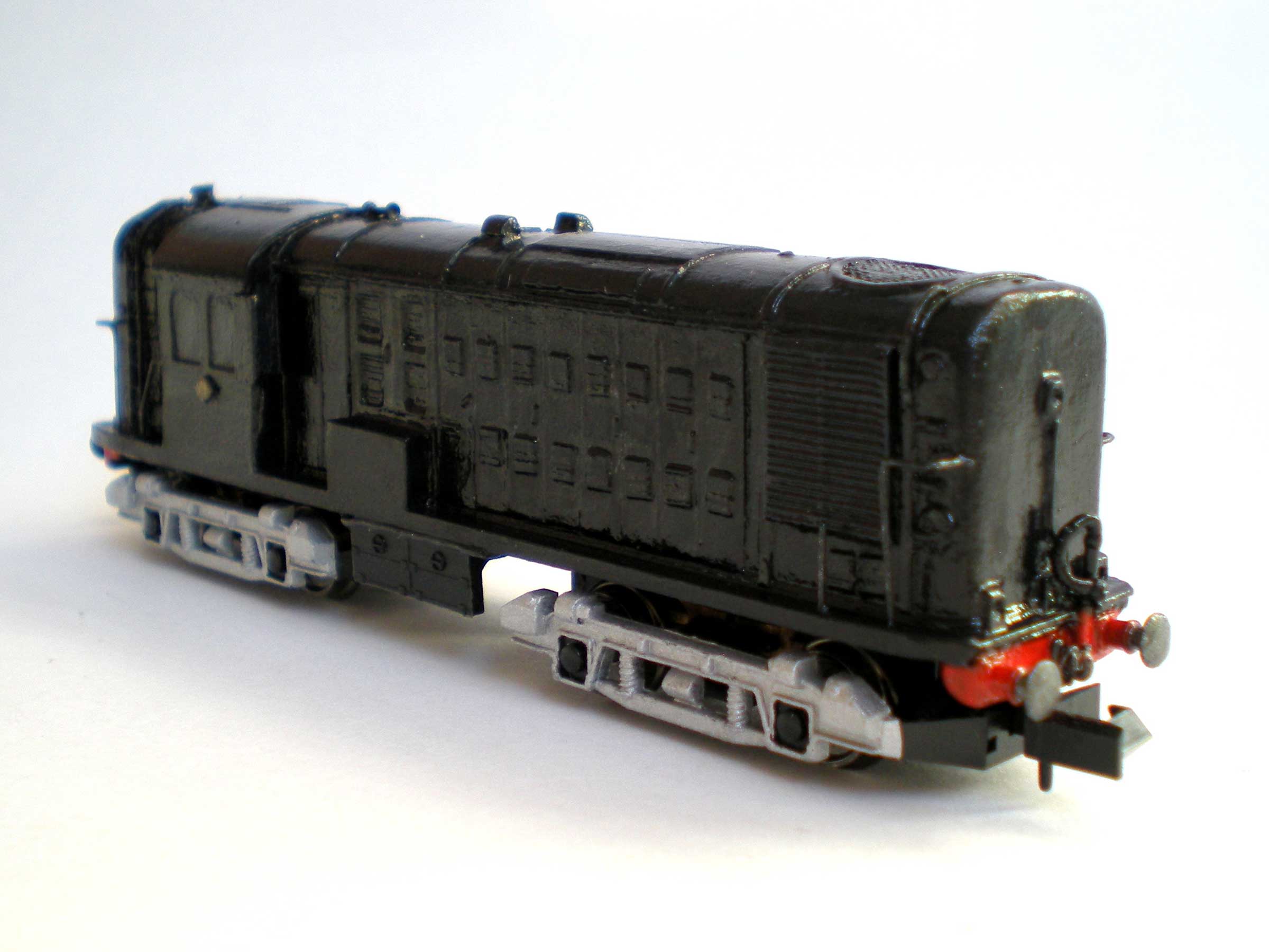
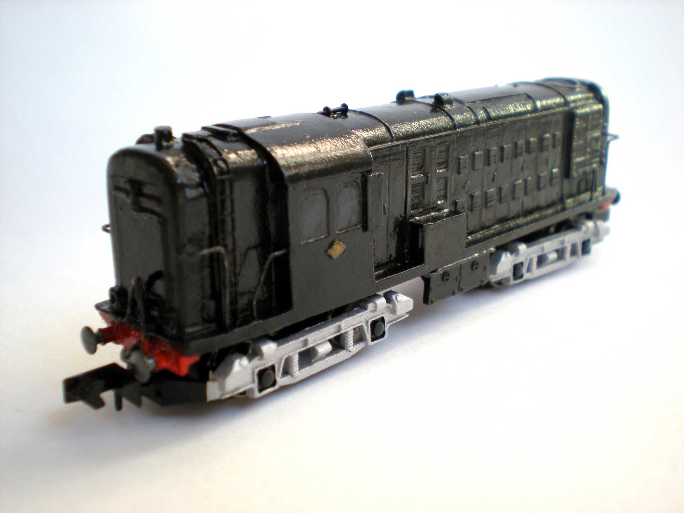
That all leaves me with one fully completed and
operational diesel locomotive kit:
The frame dirt weathering looks a little heavy
and 'scratchy' in these close-up photos, but it looks much more
acceptable to the naked eye - even in close-up!
Main Sources
Various photographs available on the internet.
There seems to be little printed information that is easily
accessible in any LMS-orientated publications (understandably), but
histories of the locomotives of British Railways should be better
supplied.
|