|
4 October 2017
by R Hobbs
One thing I get asked about is point control, and I've
a bit of a bone to chew on where that subject is concerned. Of course
there are many ways to do this. A good starting point is the Peco
booklet, Shows You How No 24: 'Operating Points and Signals'.
This provides an overview of various methods both mechanical and
electrical, and includes details about solenoid and servo-type motors.
However, I also learned quite a lot from Brian Lambert's excellent
guide to model railway electrics:
www.brian-lambert.co.uk [external link].
Solenoid point motors
Of all the methods of point operation that are
available, I use the solenoid type of motor, and in particular the
ever-popular Peco PL-10.
Essentially this consists of two wire coils which
produce a magnetic force to move the point blades back and forth.
One coil is energised to move the point one way; the other coil is
energised to move it back, and there numerous methods of energising
the coils.
Importantly, they must be energised only momentarily,
otherwise they will overheat and fail. Peco recommends its passing
contact switch for this action, which when pulled fires a pulse of
power to the relevant coil. There are also other methods; such as
using biased centre-off switches, twin push-to-make buttons, or the
probe and stud system which provides the pulse when a live probe is
momentarily touched onto a metal stud on the control panel.
In addition a capacitor discharge unit (CDU) in the
circuit will boost the momentary power and ensure that the solenoids
latch over completely. Further options exist: one in particular uses
opposing diodes connected to the point motor terminals in such a way
that only one control wire is required (instead of the usual two -
one to each coil). An example of this sort of circuit was described
by Hugh Norwood in the December 2015 issue of Railway Modeller.
Brian Lambert also shows a similar twin diode circuit
on his web page. In that example he places a capacitor in the control
wire so that he can use a simple two-way switch (SPDT) instead of a
passing contact or centre bias switch. In basic terms, the capacitor
is discharged through one coil when the two-way switch is thrown,
creating the momentary pulse of power required to change the point.
Switch the two-way switch back, and this time the capacitor charges
up immediately, creating a momentary pulse of power through the other
coil, thereby switching the point back.
When the capacitor is fully charged (or discharged)
the current stops flowing through the coils, so there is no danger
of them overheating. The fitting of the capacitor has a dual effect
in that it simulates the action of a passing contact switch and also
acts as a mini-capacitor discharge unit.
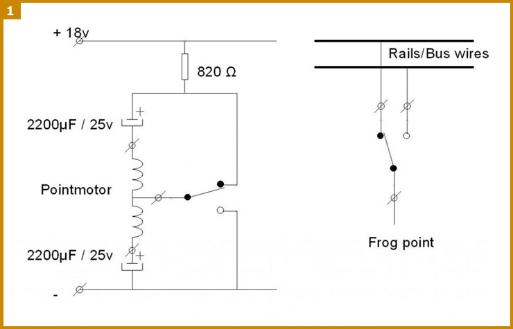
All good so far. Using these circuits as a starting
point, I developed the idea further. I dispensed with the opposing
diodes and arranged the wiring to the solenoids so that the common
terminal could be switched either to the control wire (+V) or the
return wire (0V) and fitted a capacitor in series with each coil,
so that I too could use a two-way switch. Fig 1 shows the general
principle for a single point motor.
Frog polarity switching
Now, if you're using electrofrog points and don't
want to rely on the point blades for frog switching, then you need
to fit an auxiliary switch to the point motor in order to change the
frog polarity at the same time.
Peco recommends its PL-13 auxiliary switch which
is attached onto the bottom of the PL-10 points motor. These work
very well but have been known to fail through age, dirt, and
oxidation. There are other options, such as using industry standard
micro-switches, but wouldn't it be useful if we could just have one
switch action on the control panel for simultaneous point motor
operation and frog polarity changing?
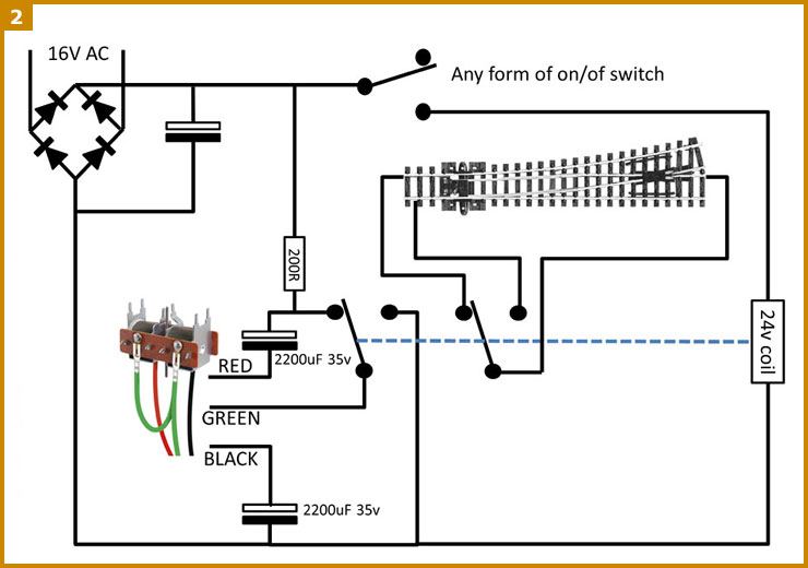
Hold onto that thought, as this is where something
called a relay comes in. By incorporating a miniature relay with
twin SPDT switches, it is now possible to switch both the point
motor and the frog polarity simultaneously, simply by energising
the relay - and guess what? All you need to be able to energise
the relay is a simple on-off switch (SPST). This can be installed
in your central control panel and just one control wire from the
switch to the corresponding relay is required. The +V and 0V
conductors are installed as bus wires around the layout. A schematic
circuit diagram for a single point is shown in Fig 2.
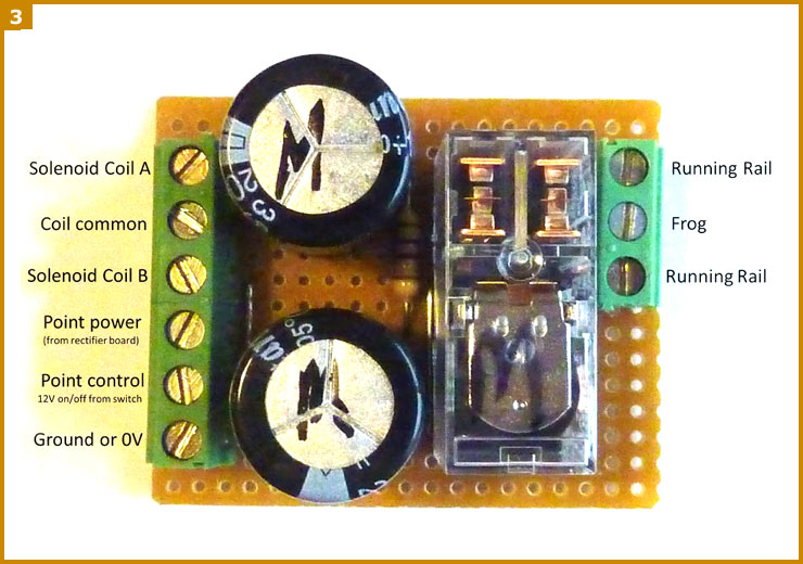
For each point I built a modular circuit board,
assembling the components on stripboard. Each module is identical and
is simply fitted near each point, being connected to the power and
common bus wires and the respective solenoid coils and frog. Figs 3
shows an example of one of the modules and Fig 4 shows the stripboard
circuit diagram.
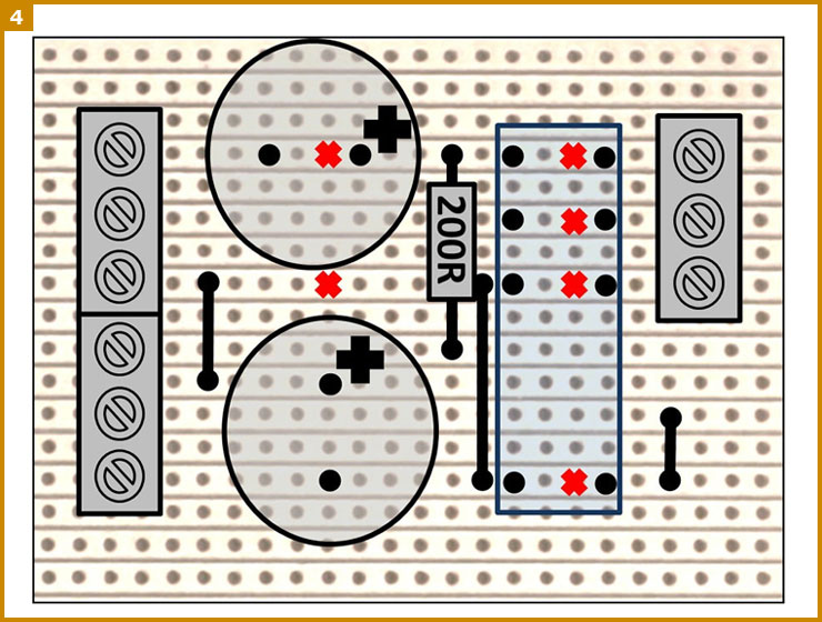
Notes on the circuit: the red crosses mark a cut in the stripboard
track to create an electrical break. The black crosses denote the
polarity for the capacitors. Failure to deal with either the cut or
capacitor polarity correctly results in melting or popping! The
resistor can be any value between 47R and 820R - the lower the
value, the faster the recharge speed. Capacitors are 2200μF
35V-rated for this 20V power supply version. (As an alternative you
could have a separate, higher voltage power supply, in which case
reduce the value of the capacitors. I use 1000μF 50V-rated
capacitors on a 40V supply for historical reasons on Bridgebury
Gate. However, many may consider a higher voltage to be a little
precarious!)
Visual indication
Finally, when thinking about your control panel, it is useful to be
able to see which way your points are set.
Both passing contact switches or Brian Lambert's
circuit can indicate that, but the probe and stud method cannot, not
without some sort of feedback circuitry. I decided that a rotary
switch fitted with a directional knob similar to the one shown in Fig
5 would do the trick, and all my point switches on Bridgebury Gate's
mimic control panel use these - I can see at a glance which way the
points are thrown.

Setting up
With the electronic module made up and installed
on the layout, connect the point motor leads and the bus wires to
the relevant terminals.
Set the corresponding rotary switch that's now
fitted onto the panel to what you define as the normal route for
trains, and switch on the power. If the point switches the opposite
way to what you require then simply reverse the red and black wires
between solenoid coil terminals A and B (see Fig 2, above).
You should now have the point working the way you
want it. The next step is to connect the frog and running rail wires
to the relevant terminals. Again, if you get a short circuit on the
track, then simply reverse the running rail wires and re-test.
From there on it's also possible to add basic route
setting, by adding a diode to operate each point that you want to
fire from a single switch that gives you that route. Likewise you
can slave points together by connecting the control wire from two
or more points to one switch. The point is simply on/off controlled
- now that's simple!
In use
There is one disadvantage - which is also common with the other
circuits I have mentioned. When you power up your layout at the
start of a session, the points may not necessarily be in the state
shown by the switch, which is due to some solenoids being triggered
randomly as the capacitors charge up at switch-on.
Don't worry! It's easy to deal with! Simply reset by switching each
point over and back. This lines up the point with the switch and
it stays that way until you switch your layout off again. Unless
you have a huge number of points, it's not much of a hardship to
do this at the start of every operating session, and as it also
checks that each of your points are working.
Pros and cons
Although these modules are more involved when it comes to building
and installing them, and they are more costly than conventional point
solenoid wiring, they have several advantages:
- each point has its own CDU
- the mechanism is very robust
- it can be extended to provide route selection from a
single switch
- additional relays can be added to operate signals
- only one control wire has to be run from the control
panel
- switches can be arranged on the panel to show which
way the point is set
- only low current control signals pass to the relay
modules; the high current pulses are confined to the respective point
circuitry.
The modules are, however, not readily suitable for DCC with live
frogs as there can be a tiny lag between the solenoid switching
the blades and the relay switching the frog polarity. This can be
sufficient to cause a momentary short circuit in the rails and
trigger the cut-out on the DCC system.
As with solenoids in any wiring configuration, they are not slow and
realistic in operation in the way that a servo or a wire-in-tube
system might be. The Model Electronic Railway Group has developed
its own PD3 point driver which controls the point from a single switch,
also allowing the control panel to reflect the exact position of the
points. It also has sufficient contacts for the frog polarity too,
although you do have to be a member of MERG to be able to buy the
kit.
Finally, for those modellers who really are interested, the
stripboard design has been developed into a printed circuit board
by Malcolm Crabbe. He has produced both bare boards and full kit
versions, called the Solenoid Point Universal Driver or SPUD-1,
which are available to purchase online at:
micro-heli.co.uk [external link].
This article was originally written by R Hobbs for his own website.
It is reproduced here with permission (and encouragement!) and has
also been reproduced in the October 2017 edition of Railway
Modeller (pp 826-827).
|